Welded Connections (and weld stress in them) are crucially important for safety and durability of steel structures. Here we will show a theory and FEA approach for weld stress calculation
Introduction
Welding – is a fabrication process, that joins materials (usually metals) through the high heating. This is one of the most popular approaches in designing of steel structures because of a few main reasons:
- Welding – is the joining method that creates a truly one-piece structural member out of several components, which are transferring the loads effectively between each other;
- A minimum amount of material is needed for welding to provide the efficient connection.
Although this long-known approach makes our life easier, the welded connections remain to be the critical components of safety and durability of steel structures. When failure occurs in a welded connection, it’s no longer able to transfer the loads (reactions) from one structural element to another and therefore perform it’s intended design functionality. In some events it may even lead to the overall collapse of the structure itself, so the engineer should have knowledge in metallurgy, weld design, welding process, fatigue, welding procedure variables etc., to prevent these situations. Fortunately, the appropriate design codes / standards are available (e.g. IIW, Eurocode 3, DNV, FKM, DVS etc.) and specify the minimum requirements to be met – for instance in weld strength check and fatigue check of the welds.
Both of these checks are impossible without of calculated weld stress in the interested connection, which can be easily computed by the Finite Element Analysis using a general CAE package, like Ansys, Femap, Simcenter 3D etc.
Finite Element Analysis (FEA) Approach to Weld Stresses
Models with either thin plate or shell elements or with solid elements may be used to calculate the weld stress depending on the complexity of the task.
The first method (with plate elements), which is based on the relatively simplified modelling approach, is the most common one and doesn’t require to model the welds.
This option is allowed by most of the standards, e.g. International Institute of Welding (IIW) & Det Norske Veritas and Germanischer Lloyd (DNV GL) (see below):
IIW standard doesn’t prescribe the welds modelling for simplified models, except for cases where the results are effected by local bending, e.g. due to an offset between plates or due to a small distance between adjusted welds.
If your FE model contains this exceptional case, then welds may be included by vertical or inclined plate elements having appropriate stiffness or by introducing constraint equations or rigid links to couple node displacements (see some examples below).

DNV GL allows method B (see below) for modelling with shell elements without any weld included in the model:
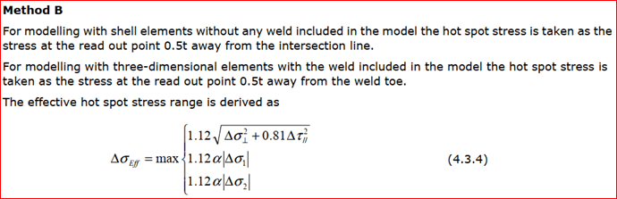
In this case, the relevant treatment of the results is recommended to be made – stress is taken at the read out point 0.5t away from the intersection line (see below).

Based on the engineering experience, this method gives the outcomes, which are close to reality, but if much more accurate results are required – particularly for complex cases, prismatic solid elements may be used. This type of elements has a displacement function allowing steep stress gradients as well as plate bending with linear stress distribution in the plate thickness direction.

It requires the volume modelling of the welds, which provides the weld stress over its cross section. However, it’s often quite “challenging task” because of weld shape to be analyzed, which makes a crucial influence on the results (i.e. weld stress).
FEA drawback
Along with such a big advantage as FEA analysis, come a couple significant drawbacks:
1. All programs, which are based on the finite element method approach (e.g. Ansys, Femap, Simcenter 3D etc.) provide stresses in the local element coordinate system, while calculated stresses should be oriented into the weld direction for performing a weld strength or fatigue checks on welds (see below);

X – parallel to the weld.
Y – perpendicular to the weld.
2. Engineers should manually define / find all welds in the model.
In models with only several welds it’s relatively not hard to spend some time to define / find them, reorient stresses in finite elements into the weld direction and then execute the required checks. However, this process should be repeated for the large number of load cases prescribed by the standards, which makes it already not so simple, while in case of hundreds / thousands welded connections, which the real structures normally include, this process becomes a time-consuming complex task.
SDC Verifier solution for FEA analysis of welds
This boring engineering routine is completely automated in SDC Verifier, which works directly within your favorite FEA software.
How do we deal with this?
After the all welds are automatically recognized with help of Weld Finder tool (just in few clicks), all stresses in your model are converted automatically into the weld direction, without reorientation. Weld Finder is a part of SDC Verifier Recognition Tools. Weld Stresses are therefore implemented as a separate category. All tables/plots for stresses also can be created for the weld stresses:

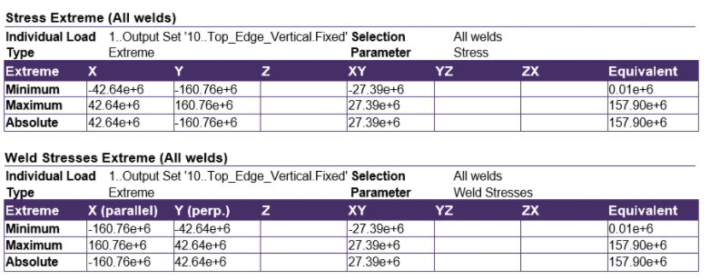
The first table below shows extreme stresses in the standard element orientation and the second table shows the converted stresses in the weld direction:
On the left plot, the stresses in the element direction are shown and the weld stresses plot is shown at the right page. You can see that only weld elements are converted. For the elements that don’t belong to the weld, the stresses are shown in the standard element direction:

To avoid confusion, the user can also plot only the stresses in the weld elements (using Rule-Based Selector):

Besides, except of already implemented list of standards for the verification of welds (like DNV, Eurocode 3, EN13001, FEM 1.001, FKM, DVS, DIN 15018, ASME VII etc.), you can create your custom checks, where it’s possible to use the weld stresses by using the Sweld variable. For example, different allowable stresses for shear stress and the normal stresses parallel and perpendicular to the weld orientation can then easily be accounted for:

And for fatigue checks on welds, the stress variation (SweldDelta) of a group of results in the parallel, shear and perpendicular directions can be calculated as shown in the example below:

Other weld parameters, which are required for the Weld Strength Check execution, can be easy set up in the Weld Strength Settings of Weld Finder tool, for instance:
depending on the weld types (e.g. fillet weld / double fillet welds, groove welds with partial / full penetration etc.) and weld size (legs, penetration depth etc.), the results of strength check are different, so it’s possible to take these details into account as well.
Note: Size of a fillet weld is usually determined by measuring the leg size, even though the weld is designed by determining the required throat size. In case of equal-legged and flat-faced fillet weld applied to plates that are perpendicular to each other (90°), the throat dimension is calculated by multiplying the leg size by 0.707 (i.e., sine 45°).
Conclusion
SDC Verifier allows you to check the weld stresses quickly directly within your favorite FEA software, like Ansys, Femap, Simcenter 3D and perform the required checks on welds according to engineering industry standards (DNV, Eurocode 3, EN13001, FEM 1.001, FKM, DVS, DIN 15018, ASME VII etc.) automatically! Completely automatic recognition of all welds in your model in combination with these capabilities can save you days, weeks or even months!

