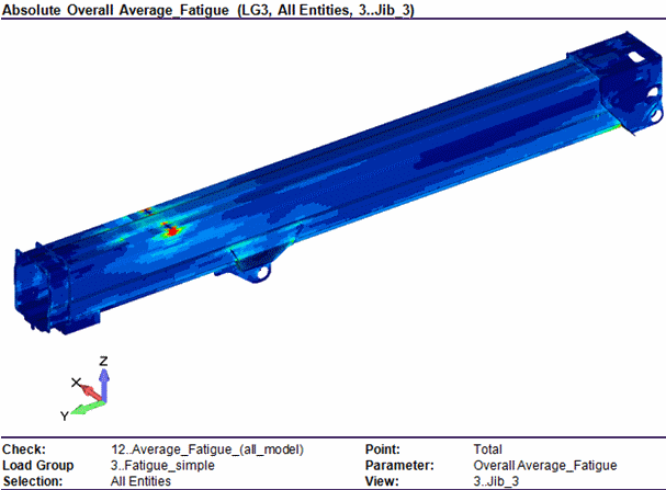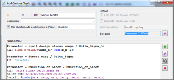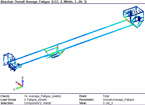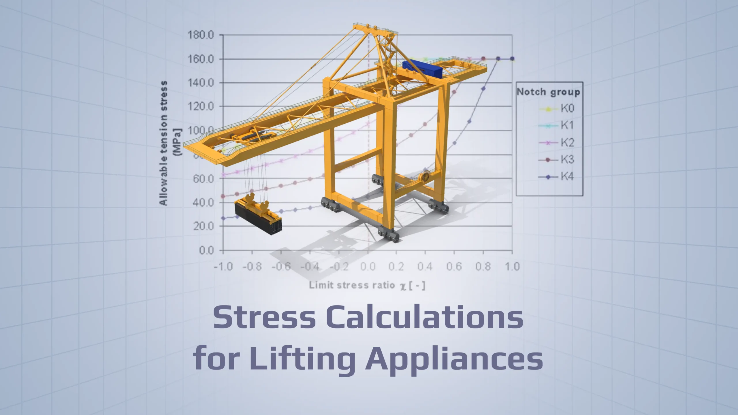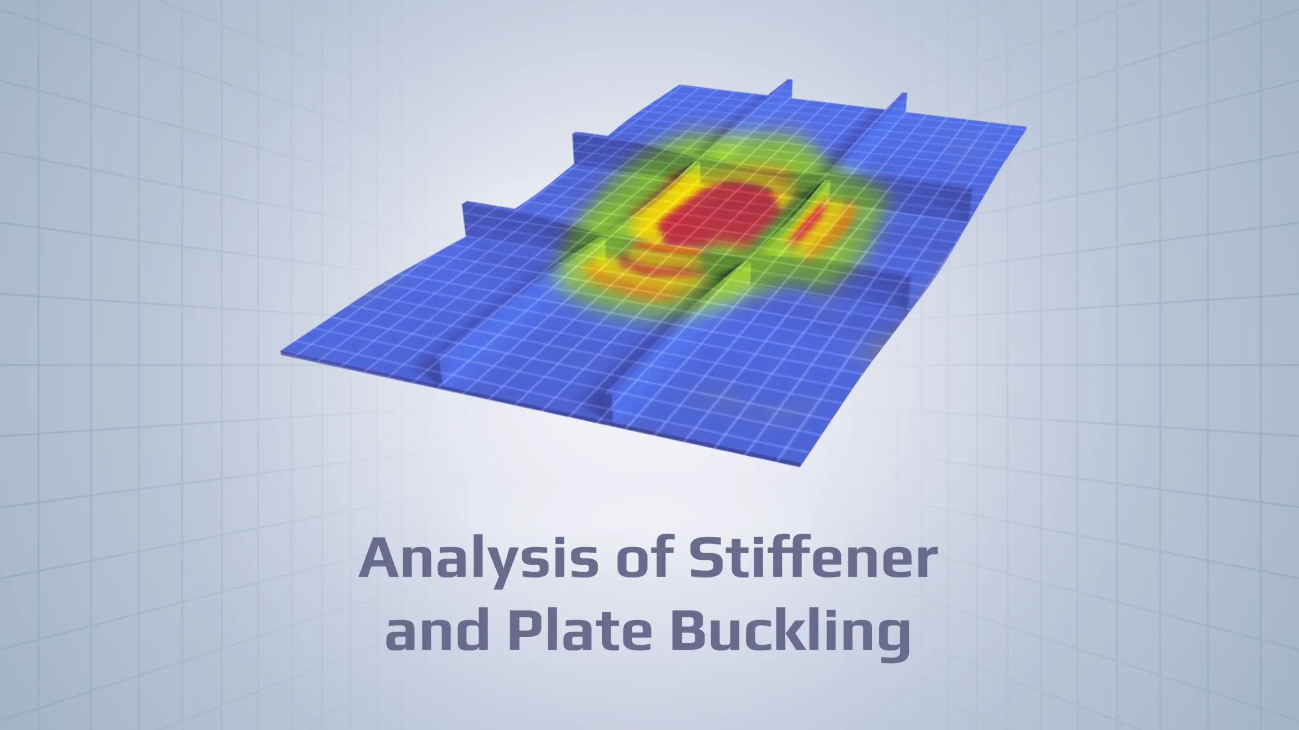
Four checks according to EN280/13001 were performed for Crane: Static strength, Static strength for welds, Fatigue check and Fatigue check for welds:
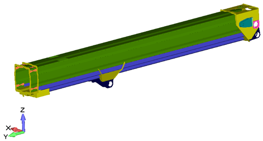
Proof of static strength
The limit design stress ƒRd, used for the design of structural members, shall be calculated from:
| ƒRdσ= | ƒy | for normal stress |
| ϒRm | ||
| ƒRdτ= | ƒy | for shear stress |
| ϒRm√3 |
with ϒRm=ϒm×ϒsm
where
| ƒy | is the minimum value of the yield stress of the material |
| ϒsm | is the specific resistance factor for material as follows |
For non-rolled material:
ϒsm=0.95
For rolled materials (e.g. plates and profiles):
| ϒsm=0.95 | for stresses in the plane of rolling |
| ϒsm=0.95 | for compressive and shear stresses |
For tensile stresses perpendicular to the plane of rolling:
Material shall be suitable for carrying perpendicular loads and be free of lamellar defects
ϒsm=1.0 for plate thicknesses less than 15 mm or material in quality classes Z25 or Z35 in accordance with EN 10164:2004.
ϒsm=1.16 for material in quality classes Z15 in accordance with EN 10164:2004.
ϒsm=1.34 for materials without quality classification in accordance with EN 10164 but, conforming to classes S2 and E3 10160:1999.
ϒsm=1.50 without quality classification of through-thickness property.
Proof for structural members
For the structural members to be designed it shall be proven that:
σSd ≤ ƒRdσ and τSd ≤ ƒRdτ
where
| σSd, τSd | are the design stresses. The von Mises equivalent stress may be used as the design stress instead. |
| ƒRdσ, ƒRdτ | are the corresponding limit design stresses in accordance with clause 1. I case von Misses is used, ƒRdσ is the limit design stress. |
In a case of plane states of stresses when von Mises stresses are not used it shall additionally be proven that:
where
| x,y | indicate the orthogonal directions of stress components. |
Implementation
S.eqv takes into account all stress direction.
Gamma_m – specific resistance factor for materials, which described above.
yield – yield stress of the materials.
Results
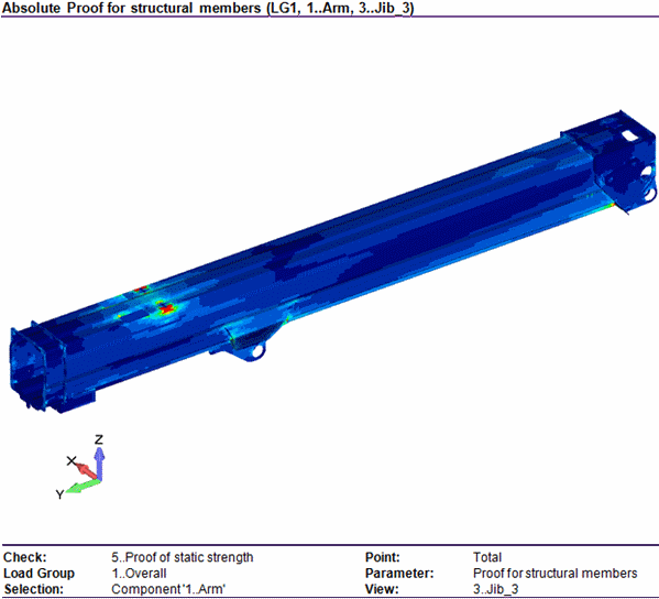
On pictures below shown results of the Static check for all model. All results above 1 are unacceptable.
Proof of static strength (welds)
Depending on the equation number given in table 1, the limit design weld stress ƒw,Rd shall be calculated entirely by:
| ƒw,Rd= | αw׃y |
| ϒm |
of by
| ƒw,Rd= | αw׃uw |
| ϒm |
where
| αw | is a factor given in table 1 in dependence on the type of weld, the type of stress and the material. |
| ƒy | is the minimum value of the yield strength of the connected members under consideration. |
| ƒuw | is the ultimate tensile strength of the weld material (all weld metal). |
Table 1 – Factor of limit weld stress
| Type of weld material | Direction of stress | Type of weld | Type of stress | equation number | ƒy≤ N/mm2 |
αw ƒy>420 ƒy<930 N/mm2 |
ƒy≥930 N/mm2 |
|---|---|---|---|---|---|---|---|
| Matching (ƒy refers to the welded members) |
Stress normal to the weld direction | Full penetration weld | Tension or compression | 21 | 1.0 | 0.93 | |
| Partial penetration welda | Tension or compression | 21 | 0.90 | 0.85 | |||
| Stress parallel to the weld direction | all welds | Shear | 21 | 0.60 | 0.55 | ||
| Under-matching (ƒy refers to the weld material) |
Stress normal to the weld direction | Full penetration weld | Tension or compression | 22 | 0.80 | 0.85 | 0.90 |
| Partial penetration welda | Tension or compression | 22 | 0.70 | 0.75 | 0.80 | ||
| Stress parallel to the weld direction | all welds | Shear | 22 | 0.45 | 0.50 | 0.50 | |
The values of αw are valid for welds in quality C of EN ISO 5817:2007 of better.
The proof of the connected members, in accordance with 3.5.1 is always required in addition to the proof of the weld, in accordance with 3.5.4. In a case of connected members from different materials, the proof shall be made for each member separately.
For the definition of full penetration and partial penetration, weld see EN ISO 17659.
Matching welds material: weld material with ultimate strength equal or better than those of connected members.
Under matching welds material: weld material with ultimate strength less than those of connected members.
The welds joining parts of built-up members, e.g. flange-to-web connections, may be designed without regard to normal stress parallel to the axis of the weld, provided the welds are proportioned to accommodate the shear forces developed between those parts.
An asymmetric weld is not recommended, However, if used connected members shall be supported so as to avoid the effect of load eccentricity on the weld.
Proof for weld connections
for the weld to be designed it shall be proven that:
σw,Sd and τSd ≤ ƒRdσ
where
| τSd, σw,Sd | are the design weld stresses. |
| ƒw,Rd | is the corresponding limit design weld stress. |
Implementation
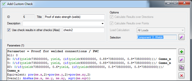
With a weld yield stress of 735 MPa, the allowable static stress in a weld can be summarized as follows:
| Stress type | Yield connected material | ||
|---|---|---|---|
| Matching | Undermatching | ||
| below 735 Mpa | up to 930 Mpa | above 930 Mpa | |
| S_normal | yield | 0.85×735 | 0.9×735 |
| T_shear | 0.6×yield | 0.5×735 | 0.5×735 |
Checks for weld were done for normal and shear stress type. X and Y are normal stress and XY – shear stress in welds. Also was calculated equivalent stress for all direction. On results, plots show overall results.
Results
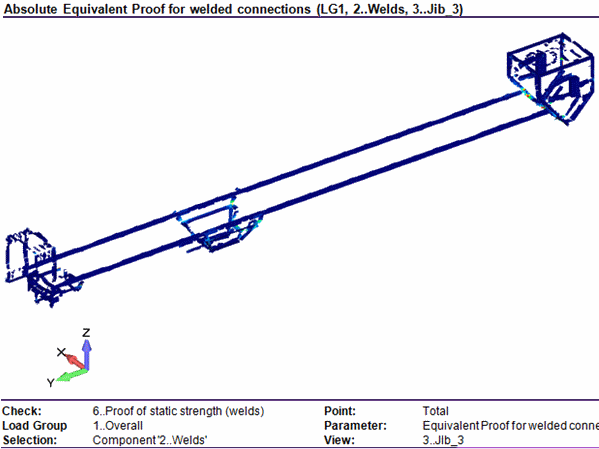
On pictures below shows results of a Static check for welds. All results above 1 are unacceptable.
Fatigue check
For the detail, under consideration, it shall be proven that:
ΔσSd ≤ ΔσRd
ΔσSd = maxσ – minσ
where
| ΔσSd | is the maximum range of design stresses. |
| maxσ, minσ | are the extreme values of design stresses (compression stresses with negative sign). |
| ΔσRd | is the limit design stress range. |
The limit design stress range shall be calculated from:
| ΔσRd = | Δσc |
| ϒmf×3√S3 |
where
| ΔσRd | is the limit design stress range; |
| Δσc | is the characteristic fatigue strength of details with m = 3; |
| S3 | is the classified stress history parameter; |
| ϒmf | is the fatigue strength specific resistance factor; |
For the most severe ϒmf = 1.25 and the values of ΔσRd in dependence on the class S and Δσc.
Implementation
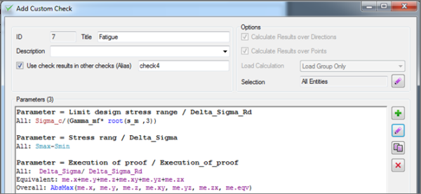
Explanations for all parameters in check see above.
Results
On pictures below shown results of Fatigue check for all model. All results above 1 are unacceptable.
Fatigue check (welds)
Implementation
The explanation for all parameters in check see above.
Results
On pictures below shows results of Fatigue check for welds. All results above 1 are unacceptable.


