In structural engineering, the bending moment is a critical concept used to analyze the behavior of beams, columns, and other structures under external loads. It refers to the rotational force or moment applied to a structural element that causes it to bend. Understanding the bending moment is essential for engineers to ensure structures’ strength, stability, and integrity.
Understanding the Concept of Bending Moment
Before diving into the details, let’s break down a bending moment’s definition and fundamental principles.
Definition and Basic Principles
A bending moment (M) is the internal resistance of a structure to bending. It is caused by external forces acting on a structural member, such as a beam or column, which create tension on one side and compression on the other. The bending moment is typically measured in force multiplied by distance (e.g., Newton-meters [N-m] or pound-feet [lb-ft]).
When external loads are applied to a beam or column, they induce internal forces that lead to bending. Engineers quantify the magnitude of these forces using the bending moment to ensure that the structure can maintain equilibrium and resist deformation.
For a more intuitive explanation of bending moments without complex mathematics, watch this video:
This video offers simple examples to help build a clear understanding of what bending moments represent in real engineering contexts.
Importance in Structural Engineering
The bending moment plays a crucial role in designing safe and efficient structures. By analyzing bending moments, engineers can prevent excessive deformations and material failure and ensure the structure can carry its intended loads. The calculation of bending moments is key in selecting materials, determining support conditions, and designing load-bearing components in industries like civil construction, mechanical engineering, and aerospace.
Software like SDC Verifier streamline this process by automating bending moment calculations and other structural verifications, ensuring compliance with various industry standards.
Applications in Engineering Fields
Civil Construction
In civil construction, bending moments help design structural elements like beams and columns, essential in bridges, buildings, and other large-scale projects. For example, engineers must consider the forces exerted by vehicles passing over a bridge when designing it. By calculating the bending moments at various points along the bridge, they can determine the appropriate size and strength of the beams or girders needed to support these loads.
Mechanical Engineering
In mechanical engineering, bending moments are critical for designing machine components such as shafts, gears, and other load-bearing parts. When designing a gearbox, engineers analyze the bending moments on the gears to ensure they can handle the transmitted power without failing. This analysis allows them to choose suitable materials and dimensions for reliable and efficient performance.
Aerospace Engineering
In aerospace engineering, bending moments are vital for designing lightweight yet strong aircraft components, like wings and fuselages. During flight, aerodynamic forces create bending moments in the wings. Engineers analyze these moments to ensure that the wing structure can withstand the stresses imposed by lift and drag without failing. Proper material selection and reinforcement strategies are crucial in this process.
Factors Influencing Bending Moment
Several factors affect the magnitude and distribution of bending moments in a structure:
Cross-Sectional Shape and Moment of Inertia
A structural member’s cross-sectional shape and moment of inertia significantly impact its response to bending loads. The moment of inertia represents the member’s ability to resist bending, with larger values indicating better resistance. Engineers must carefully consider the cross-sectional geometry to ensure the member can withstand the expected forces.
Material Properties
The material properties of a structural member, such as elasticity and yield strength, influence its behavior under bending loads. Stiffer materials are more resistant to deformation, reducing the bending moment. Selecting materials with the appropriate properties is essential for achieving optimal structural performance.
Load and Support Conditions
The distribution of loads and the support conditions of a structure determine the bending moment. Different support types create varying bending moment distributions, such as simple supports, cantilevers, or fixed supports. Additionally, concentrated and distributed loads affect the calculation of bending moments.
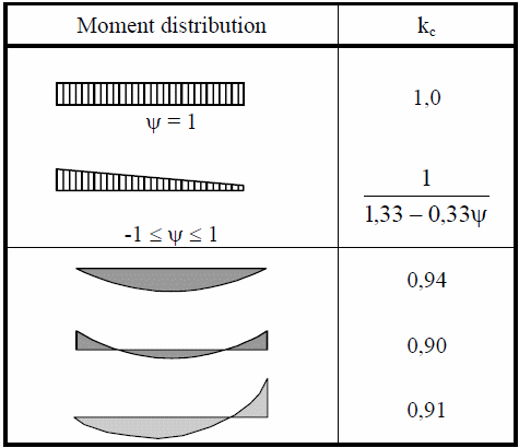
The following table illustrates different moment distributions and their corresponding kc factors. These values are used to calculate the reduction in bending moments depending on the moment distribution along the beam, which is essential for compliance with Eurocode 3 standards.
Temperature Effects
Temperature changes can cause structural members to expand or contract, introducing internal stresses and additional bending moments. Engineers must account for these effects, especially in structures exposed to varying environmental conditions, to ensure stability and safety.
Types of Bending Moments
Bending moments can be classified based on their characteristics:
Positive and Negative Bending Moments
- A positive bending moment occurs when a member is sagging, with compression on the top and tension on the bottom.
- A negative bending moment happens when the member is hogging, with tension on the top and compression on the bottom.
The image below illustrates the key types of forces and moments in structural elements: axial force, in-plane bending moment, and out-of-plane bending moment. These distinctions are crucial for understanding the different stresses and deformations that occur in a beam under various loads.
Concentrated and Uniform Bending Moments
- Concentrated bending moments occur at specific points on a member, creating localized deformation.
- Uniform bending moments are distributed evenly along the span of the member, resulting in consistent deformation.
Moment Ratio and Bending Moment Calculation in SDC Verifier
In advanced structural analysis, engineers often use moment ratios to calculate moment reduction factors and verify compliance with industry standards. SDC Verifier includes tools that calculate important factors like Kc and Bm (Eurocode 3), Cb (AISC), and others from standards such as API 2A RP, ISO 19902, and NORSOK N004.
These tools allow engineers to perform complex moment ratio calculations efficiently. For example, SDC Verifier calculates the lateral-torsional buckling modification factor (Cb) for AISC standards and the equivalent uniform moment factor (Bm) for Eurocode 3. This automation saves time and ensures accuracy in compliance checking for structures under bending loads.
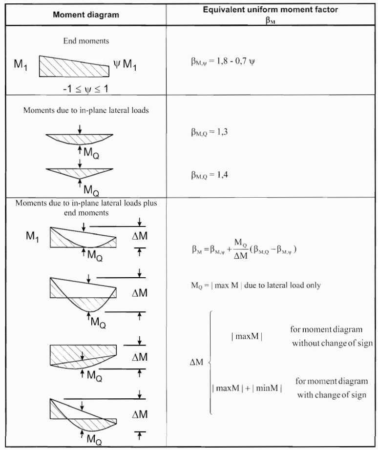
The diagram below illustrates various moment conditions and the corresponding Equivalent Uniform Moment Factor (βM). This factor helps engineers adjust calculations for complex loading conditions, such as lateral loads and combined end moments, in line with structural standards.
Calculating Bending Moments
Accurate calculation of bending moments is essential for ensuring the safety and efficiency of a structure. The basic formula for calculating bending moments is:
Where:
- ( M ) = bending moment
- ( F ) = applied load
- ( d ) = distance from the point of interest to the load
SDC Verifier automates bending moment calculations as part of its broader suite of structural verification tools. Engineers can use it to model complex load scenarios, perform moment reduction factor calculations, and generate bending moment diagrams for beams and other components.
To better understand the process of drawing shear force and bending moment diagrams, which are crucial for calculating internal forces in beams, watch the following video:
This video breaks down the steps of drawing these diagrams, helping you visualize how shear forces and bending moments develop along a beam.
Bending Moment Diagrams
A bending moment diagram (BMD) visually represents the variation of bending moments along the length of a structural member, such as a beam. Bending moment diagrams help engineers identify the maximum and minimum moments, which are critical for designing safe and efficient structures. Understanding these diagrams is fundamental to assessing the structural integrity of beams, columns, and frames.
How to Construct a Bending Moment Diagram
To construct a bending moment diagram, engineers follow these steps:
-
Calculate Support Reactions: The first step is to calculate the reactions at the supports using equilibrium equations (sum of forces and sum of moments must equal zero).
-
Determine Shear Force Diagram (SFD): Before constructing a BMD, engineers create a shear force diagram (SFD). Shear forces are the internal forces that act parallel to the cross-section of a structural element, and their values must be known to calculate the corresponding bending moments.
-
Calculate Bending Moments: Using the shear force values, bending moments are calculated at different points along the member. The bending moment at any point is the integral of the shear force over the length of the beam.
-
Plot the Bending Moment Diagram: Once the bending moments are calculated, they are plotted along the beam’s length to visualize the distribution of internal forces.
Types of Bending Moment Diagrams
-
Simply Supported Beams: In a simply supported beam subjected to a uniform load, the BMD has a parabolic shape, with the maximum moment at the center of the beam.
-
Cantilever Beams: For cantilever beams, the BMD shows a linear distribution with the maximum moment at the fixed end and zero at the free end.
-
Fixed Beams: In fixed beams, the BMD exhibits negative moments near the supports and positive moments in the midspan, reflecting the bending behavior of the structure under load.
Using Bending Moment Diagrams in Design
Bending moment diagrams provide engineers with valuable insights into how a structure will respond to loads. By analyzing these diagrams, engineers can determine the points of maximum stress and ensure that the selected materials and cross-sectional dimensions can withstand the applied forces without failure.
For complex structures, software tools like SDC Verifier simplify this process by automatically generating bending moment diagrams. The tool’s advanced algorithms calculate the moments and plot them for detailed structural analysis, saving time and enhancing accuracy.
Summary
The concept of the bending moment is fundamental in structural engineering, helping engineers design beams, columns, and other structural elements to withstand external loads. Understanding how bending moments are calculated and visualized through bending moment diagrams is crucial for ensuring safety and efficiency in design.
Tools like SDC Verifier significantly enhance the bending moment analysis process by automating calculations, generating bending moment diagrams, and ensuring compliance with international standards like Eurocode and AISC. This allows engineers to focus on optimizing designs and improving the structural performance of their projects.
