In structural and mechanical engineering, beam design is a constant balance between safety, efficiency, and cost. Beams often account for much of a structure’s weight—whether in cranes, bridges, primarily buildings, offshore modules, or towers—so every kilogram saved reduces fabrication, transport, and installation costs.
Overdesign leads to wasted material and excess dead weight, while underdesign risks buckling, instability, or yield failures that compromise safety and fail code checks. Beam section optimization closes this gap, enabling engineers to reduce weight while maintaining compliance with design standards such as Eurocode 3, AISC, ISO, and NORSOK.
In structural systems, beam sections heavily influence both weight and performance. Heavier sections increase fabrication, welding, and erection costs, and require stronger supports . Optimized sections, in contrast, minimize material use while safely carrying design loads.
Mis-sizing poses two main risks. Overdesign wastes material, increases connection stresses, and raises fatigue risk without improving safety. Underdesign can trigger local or lateral-torsional buckling, excessive deflection, or yielding—issues that may not appear in simple FEA checks. Common issues include:
Transmission tower lattice members illustrate this well. Standardized angles or tubulars are easy to fabricate but often underutilized at 40–60%, adding unnecessary steel across many members. Downsizing without code-based verification risks non-compliance with Eurocode 3 limits.
Beam section optimization aligns member size with allowable utilization, reducing weight and cost while maintaining compliance with Eurocode 3, AISC, or ISO resulting in lighter, safer, and more efficient structures.
Designing lightweight yet code-compliant beams is not simply a matter of reducing cross-sectional dimensions. Engineers must contend with a range of technical challenges that affect both structural performance and regulatory acceptance.
A section may have sufficient capacity to resist applied forces (axial, bending, shear, torsion) but still fail serviceability requirements due to excessive deflection or vibration. For example, an I-beam optimized for bending resistance can meet utilization checks under Eurocode 3 but produce deflections beyond serviceability limits in long-span roof girders.
Lightweight sections are particularly sensitive to stability phenomena that are not always obvious in basic stress analysis. Typical risks include:
FEA models may indicate stresses below the material yield, but without explicit checks against the relevant code clauses (e.g., Eurocode 3 Part 1-1 §6.3.1 for column buckling or AISC Chapter F for flexural members), the design cannot be considered compliant.
Engineers may present a model showing utilization below 100% based on simple stress ratios, only to have the design rejected during audit because it does not pass detailed verification checks. Classification societies, certification bodies, and internal QA teams require transparent documentation of how each member meets the applicable code provisions.
This mismatch—where designs “look fine” in FEA but fail in reports—often results in costly redesigns, lost time, and reputational risk.
The Beam Rule Optimization Tool in SDC Verifier, structural analysis software, is specifically designed to reduce beam weight while ensuring full compliance with recognized design standards. Instead of trial-and-error resizing, it systematically evaluates candidate beam sections, materials, and stiffness properties to determine the lightest possible configuration that still passes all code checks.
At each iteration, SDC Verifier recalculates the code checks—such as capacity, buckling, and serviceability—using the updated section and material properties together with FEA results for the selected load sets. This ensures that every design iteration remains fully compliant with standards like Eurocode 3, AISC, or DNV, delivering an optimized, auditable, and code-verified result.
Engineers define which parameters are subject to beam section optimization FEA model:
During analysis, these values replace the corresponding variables in the design formulas (e.g., section modulus W, second moment of area Iy, slenderness λ, etc.).
The tool is linked to SDC Verifier’s section library, which includes a wide range of standardized profiles:
For each optimization run, the engineer sets code-based limits. These typically include:
The most common objective is to minimize cross-sectional area, which directly correlates to structural weight and material cost. However, optimization can also be set to maximize or minimize other parameters, depending on project goals. For example:
In a typical application, the engineer selects minimize area as the governing objective, with all verification checks acting as constraints. The result is the lightest feasible beam that still meets every code requirement.
Optimizing a beam section in SDC Verifier follows a clear, structured workflow that ensures efficiency, compliance, and traceability.
Before running an optimization select load cases and applicable standard. Start by defining the relevant load cases for the structure—dead load, live load, wind, or crane loads.
1. Select Optimization of the Beam
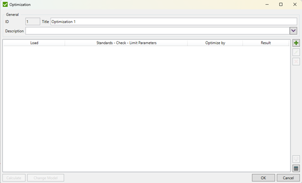
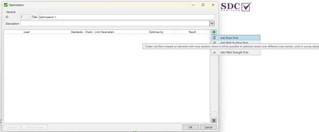
Start by defining the optimization for the beam rule.

Image: Optimization Tool window in SDC Verifier

Image: Choosing Beam Rule in SDC Verifier
2. Define Parameters
Specify which parameters the tool should optimize:
Image: Optimization window in SDC Verifier
3. Apply Standard
Image: Choosing standard, check and parameter in Optimization Tool in SDC Verifier
4. Set Limit Parameters
Input the compliance limits to ensure code adherence:
Image: Setting limits in Optimization Tool in SDC Verifier
Image: Optimization Tool window in SDC Verifier
5. Define Optimization Variables
Specify which parameters the tool should optimize:
Image: Selecting elements in Optimization Tool window in SDC Verifier
6. Choose shape cross-section (H, I, box, tubular, etc.)
Choose the first property of the model:
Image: First beam chosen for Optimization in SDC Verifier
Select rectangular tube for example from the shape library:
Image: First beam parameters for Optimization in SDC Verifier
Image: First beam detailed parameters for Optimization in SDC Verifier
Image: First beam more detailed parameters for Optimization in SDC Verifier
7. Choose the second property of the model:
Image: Second beam chosen for Optimization in SDC Verifier
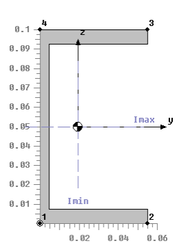
Select channel section for example:
Image: Second beam parameters for Optimization in SDC Verifier
Image: Second beam detailed parameters for Optimization in SDC Verifier
8. Choose the third property of the model:
Select another channel section for example:
Image: Third beam parameters for Optimization in SDC Verifier
Image: Third beam detailed parameters for Optimization in SDC Verifier
9. See the Calculations for Each Property
Image: Parameters of all chosen beams for optimization
10. Run Optimization and Review Results
Execute the Beam Rule optimization. The tool iteratively evaluates candidate sections and material properties, calculating utilization against all code criteria.
Image: Optimal Results option
Once complete, review the results, which highlight the optimal section, predicted weight savings, and utilization ratios.
Image: Results of the optimization
Image: Optimization results table
11. Apply Optimal Section to the Model
Integrate the optimized section back into the FEA model. This ensures the final design is both lightweight and fully code-compliant, ready for further analysis, fabrication, or audit documentation.
Image: Final window in the Optimization Tool before applying it to the model
Consider a typical transmission tower lattice structure composed of channel sections and rectangular tubes. These members are often selected from standard sections, resulting in a conservative, overbuilt design.
Image: Model of transmission tower used for optimization
Image: Mass of transmission tower
Image: Gravity load
Image: Weight of cables
Image: Wind load in X direction
Image: Wind load in Y direction
Image: Snow load
Image: HSS5X5X.313 beam
Image: Parameters of the beam
Image: UE 180 (18Y) beams
Image: Parameters of the beam
Image: UPE 120 beams
Image: Parameters of the beam
Image: UF before optimization
Image: Results based on Eurocode 3 verification
While the design is safe, over half the material is effectively “idle,” representing unnecessary cost and added dead load.
Using SDC Verifier’s Beam Rule Optimization Tool, the design was re-evaluated with:
Results:
Image: Optimization Beam ‘1.HSS5X5X.313’ HSS5XSX.188 m:1
Image: Parameters of the beam
Image: Optimization Beam ‘2.UE 180 (18 Y)’ UE 120 (12 Y) m:1
Image: Parameters of the beam
Image: Optimization Beam ‘3.. UPE 120’ UPE 100 m:1

#image_title
Image: Parameters of the beam
Image: Steel weight after optimization
Image: UF after Optimization
Image: Results of verification against Eurocode 3
This example demonstrates how beam section optimization can transform a safe but inefficient design into a lighter, more cost-effective, and fully code-compliant structure without compromising safety.
A key advantage of using SDC Verifier’s Beam Rule is the automated generation of code-compliant verification reports. Every optimized member is documented against relevant standards—Eurocode 3, AISC, DNV, or project-specific criteria—ensuring that strength, buckling, and deflection checks are fully traceable.
These reports allow designs to pass classification society reviews or internal QA checks without additional manual calculations. Engineers can also review and adjust transparent variable and limit settings, such as utilization factors, deflection limits, and material properties, giving full control over the optimization process while maintaining full compliance.
Beam section optimization is highly effective, but there are scenarios where caution is required:
Beam section optimization is a safe and effective way to reduce weight while ensuring compliance with design codes. Properly applied, it lowers material costs, simplifies fabrication, and maintains structural integrity.
Stay updated with the latest in structural verification, engineering insights, and SDC Verifier updates.