Crane Standard EN 13001-3-1+A2 Limits States and proof competence of steel structure is implemented in SDC Verifier. The standard is to be used together with EN13001-1 and EN13001-2:
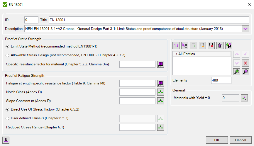
EN 13001-3-1 standard deals only with the limit state method. The allowable stress method is reliable in specific cases – for cranes where all masses act only unfavorable with linear relationship between load actions and load effects.
To account for the uncertainty of fatigue strength values and possible consequences of fatigue damage – fatigue strength specific resistance factor should be specified:
| Accessibility for inspection | Fail-safe detail | Non fail-safe detail | |
|---|---|---|---|
| Without hazards for persons b | With hazards for persons | ||
| Detail accessible without disassembly | 1,0 | 1,05 | 1,15 |
| Detail accessible by disassembly | 1,05 | 1,10 | 1,20 |
| Non-accessible detail | N/A a | 1,15 | 1,25 |
Characteristic fatigue strength (fatigue strength at 2 million cycles) and slope constant have to be defined to calculate limit design stress range:
\[\Delta \sigma _{Rd} =\frac{\Delta \sigma _{c}}{\gamma _{mf} \times \sqrt[m]{s_{m}}}\]
Where
- Δσc — Is the characteristic fatigue strength (Annex D and Annex H of standard)
- m — Is the slope constant of the log Δσ – logN curve (Annex D and Annex H of EN13001 standard)
- ϒmf — Is the fatigue strength specific resistance factor (see table above)
- sm — Is the stress history parameter
Characteristic fatigue strength
Fatigue Strength Parallel to the weld:
See how SDC Verifier calculates fatigue strength parallel to the weld
| Detail No. |
Δσc Δṫc |
Constructional detail | Requirements |
|---|---|---|---|
| 3.7 | m = 3 |  Normal stress in weld direction Normal stress in weld direction |
Special conditions:
|
| 180 | Continuous weld, quality level B | ||
| 140 | Continuous weld, quality level C | ||
| 80 | Intermittent weld, quality level C |
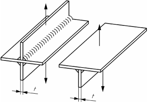
Fatigue Strength Perpendicular to the weld for welded parts:
See how SDC Verifier calculates fatigue strength perpendicular to the weld
| 3.9 | m = 345 |
|
Basic conditions:
Special conditions:
|
| 71 | Quality level B | Stress in the loaded plate at weld toe | |
| 63 | Quality level C |
Fatigue Strength Perpendicular to the weld for non-welded parts:
| 3.28 | 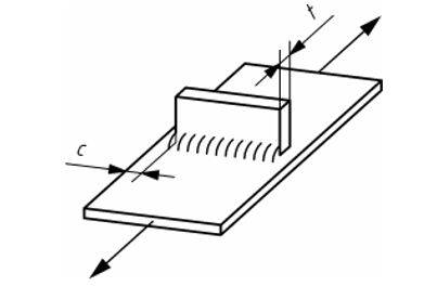 Continuous component to which parts are welded transversally Continuous component to which parts are welded transversally |
Basic conditions:
Special conditions:
|
|
| 112 | Double fillet weld, quality level B* | ||
| 100 | Double fillet weld, quality level B | ||
| 90 | Double fillet weld, quality level C | ||
| 80 | Single fillet weld, quality level B, C | ||
| 80 | Partial penetration V-weld on remaining backing, quality level B, C |
Fatigue Strength Shear direction to the welds:
See how SDC Verifier calculates fatigue strength in shear direction to the weld
| Detail No. |
Δσc Δṫc N|mm 2 |
Constructional detail | Requirements |
|---|---|---|---|
| 3.34 | m = 5 | 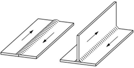 Continuous groove weld, single or double fillet weld under uniform shear flow Continuous groove weld, single or double fillet weld under uniform shear flow |
Basic conditions:
Special conditions:
|
| 112 | With full penetration | ||
| 90 | Partial penetration |
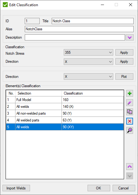
SDC Verifier defines all fatigue strength classification
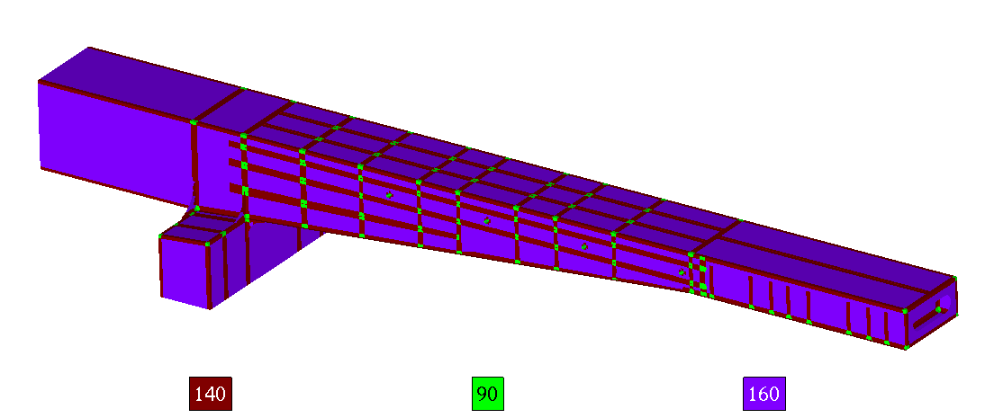
Fatigue Strength Parallel to the weld calculated in SDC Verifier
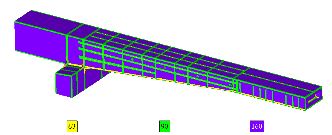
Fatigue Strength Perpendicular to the weld calculated in SDC Verifier
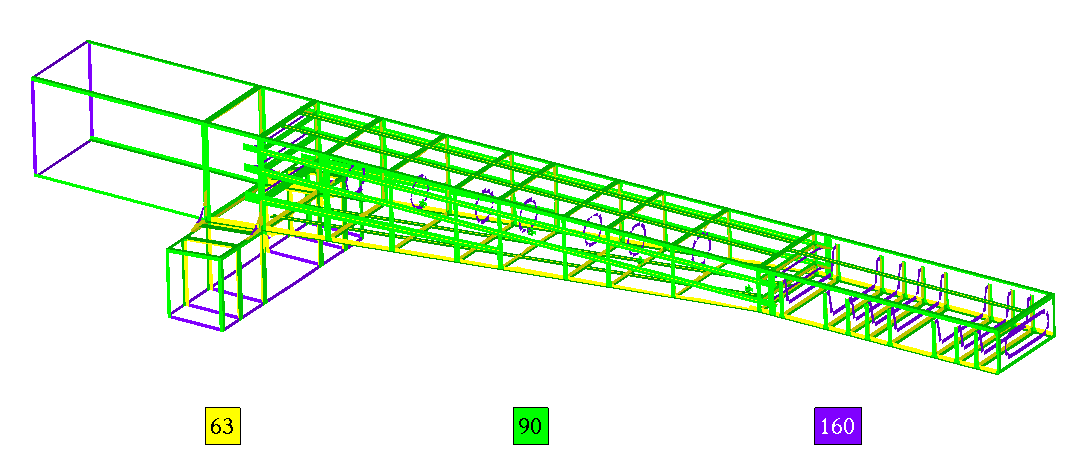
Fatigue Strength Perpendicular to the weld calculated in SDC Verifier
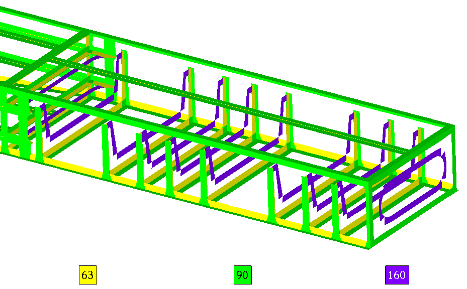
Fatigue Strength Perpendicular to the weld calculated in SDC Verifier
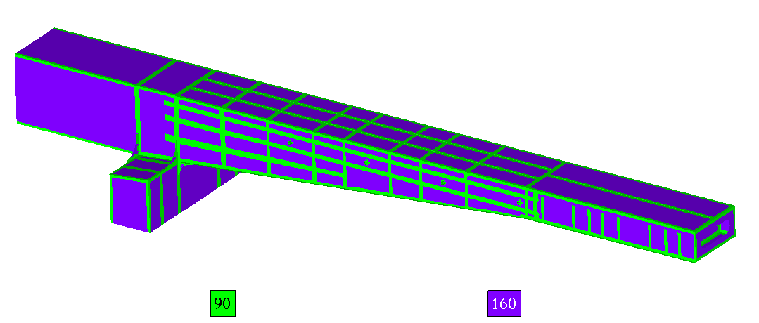
Fatigue Strength in Shear Direction to the weld calculated in SDC Verifier
For Direct use of stress history option SDC Verifier will calculate automatically stress history for slope constant 3 and 5 and use it to calculate limit design stress range. Alternatively, user can set manually class S for different directions (parallel, perpendicular to the weld).
SDC Verifier calculate cumulative damage based on Palmgren-Miner rule:
\[\sum ^{k}_{i=1}\frac{n_{i}}{N_{i}} \ =\ C\]
Where
- ni is the number of cycles accumulated at stress Si
- C is the fraction of life consumed by exposure to the cycles at the different stress levels
