For calculation of fatigue, the type of loading, the different load cycles and the calculation method, rainflow counting vs spectral fatigue calculation and allowable fatigue stress vs direct fatigue damage is important, but also the resistance of the material and in case of welded structures the influence of welds needs to be taken into account.
The DNV RP-C203 like all direct fatigue damage rule-based codes as Eurocode 3, BS 5400, IIW-1823-07 use S-N curves to calculate direct fatigue damage.
Allowable stress design codes as the EN13001, FEM 1.001, DIN15018, NEN 2018, NEN 2019, EN280, etc. use these curves as well but as fixed points on the graph to determine an allowable fatigue stress for a specific amount of loads loading logarithmic scale of cycles to failure, for more info on this see DIN15018 fatigue and EN280 fatigue.
The S-N curves are specified by the standard and take into account the type of the material, the connection or connection (welds), the stress direction and the surrounding environment. As an example, see the S-N curves for the air environment from DNVGL-RP-C203 (Edition April 2016):

S-N category depends on the type of constructional detail (non-welded, welded) and stress direction (parallel to the weld, perpendicular to the weld and shear). In the finite element model, the required information is missing and in result, the task of setting a classification can be time-consuming.
In SDC Verifier the Weld Finder tool recognizes welds automatically and converts stresses from local element direction into weld direction, which helps to set classification in different weld stress directions.
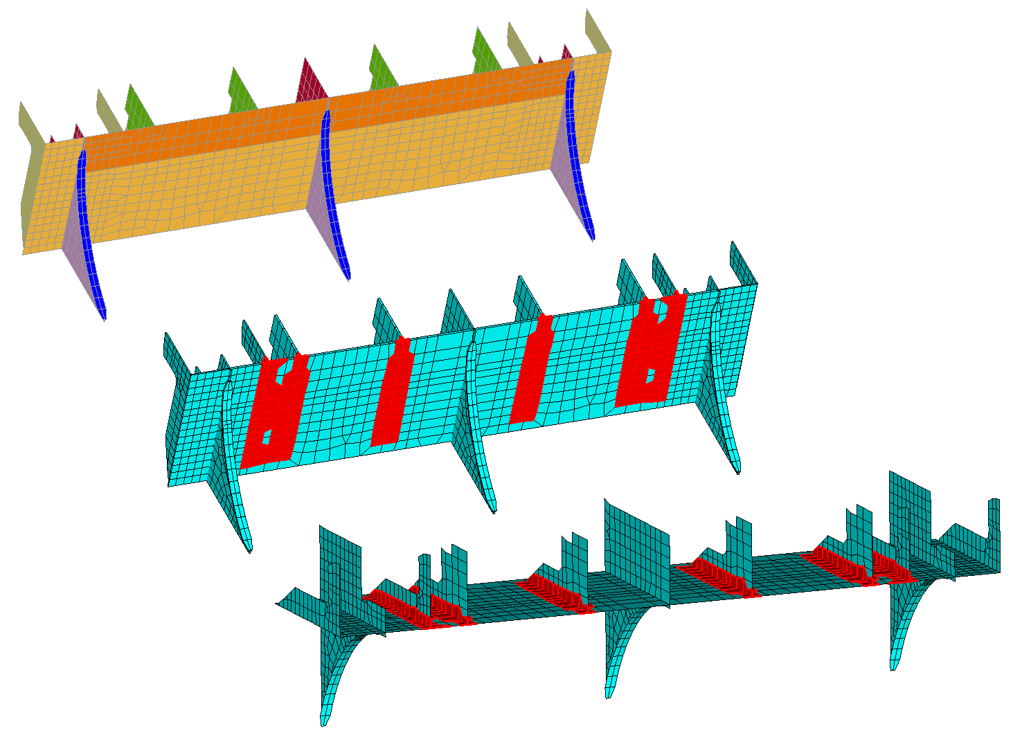
Recognized welds in the model:
Classification description
The DNVGL RP C203 method is intended for hotspot stresses, (SDC Verifier uses method B). For locations where finer meshing results in high-stress concentration factors (SCF) (point a in the picture below) the stress concentration is already calculated in the model – use category D, see description from the standard below:
For locations where finer meshing results in high-stress concentration factors (for weld tips as for example, direction II at position ‘a’) the classification is D, for all other locations the S-N class needs to be set with help of appendix A. (see below)
The text above also indicates that the 1.12 factor can be omitted for locations where nominal S_N curves are used.
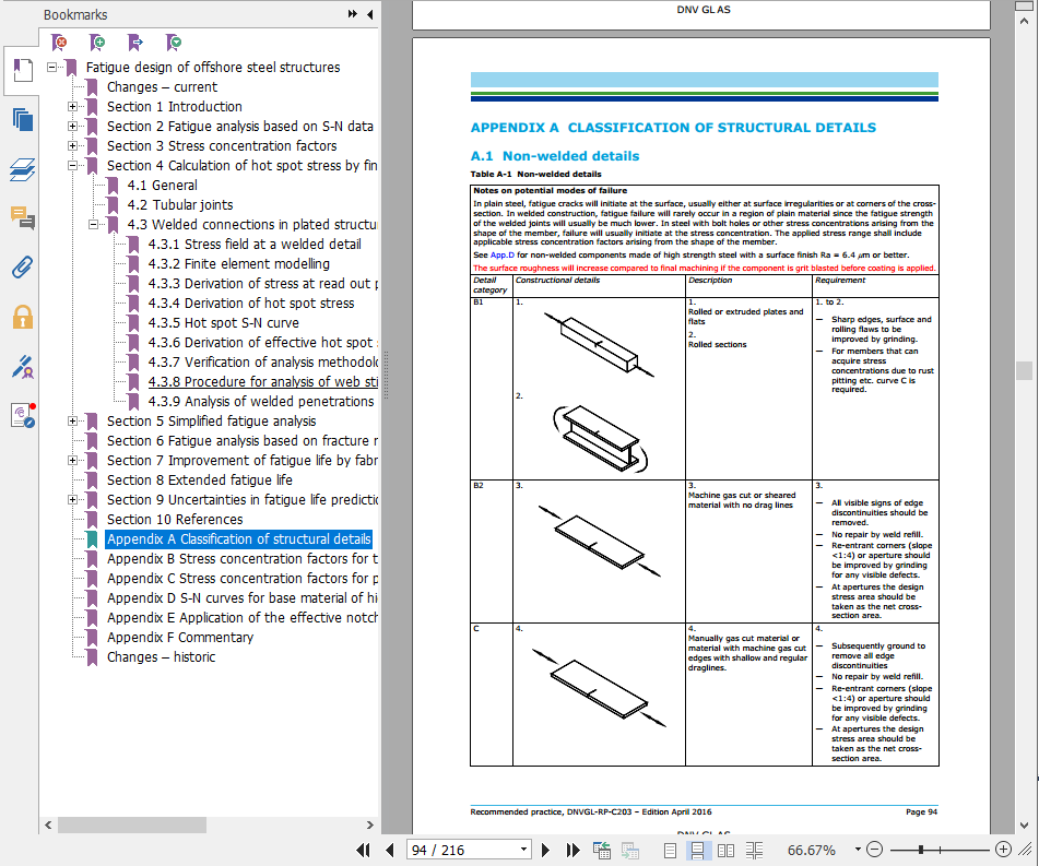
The classification for the nominal stress locations is according to specific details in the standard Appendix A:
How can this description from the standard be used, and how does this classification work for our model?
At first, we find all the relevant classification descriptions which apply to our model.
The classification depends on welded/ non-welded, type of detail/component/weld and direction of the stress. The shown classification example shows a possible classification, but do not forget to read the requirements of that classification.
For Non-welded details:
For non-welded details – category B1:
| Detail category | Constructional details | Description | Requirement |
| B1 | 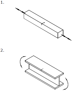 |
1.Rolled or extruded plates and flats 2. Rolled sections |
1. to 2.— Sharp edges, surface and rolling flaws to be improved by grinding. — For members that can acquire stress concentrations due to rust pitting etc. curve C is required. |
Welded details:
For welded details and for stresses parallel to the weld – category C1
| Detail category | Constructional details | Description | Requirement |
| C1 | 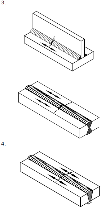 |
3.Automatic fillet or butt welds carried out from both sides but containing stop-start positions. 4. Automatic butt welds made from one side only, with a backing bar, but without start-stop positions. |
4.— When the detail contains start-stop positions use category C2 |
For Butt welds and for stresses perpendicular to the weld – category D:
| Detail category | Constructional details | Description | Requirement |
| D | 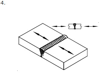 |
4.Transverse splices in plates and flats. 5. Transverse splices in rolled sections or welded plate girders 6. Transverse splices in plates or flats tapered in width or in thickness where the slope is not greater than 1:4. |
4., 5. and 6.— The height of the weld convexity not to be greater than 10% of the weld width, with smooth transitions to the plate surface. — Welds made in flat position in the shop. — Weld run-off pieces to be used and subsequently removed. Plate edges to be ground flush in direction of stress. |
For Butt welds welded from one side and stresses perpendicular to the weld – category W3:
| Detail category | Constructional details | Description | Requirement |
| W3 | 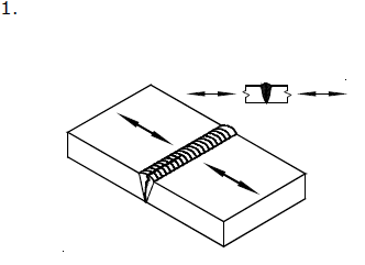 |
1.Butt weld made from one side only and without backing strip. |
1.With the root proved free from defects larger than 1-2 mm (in the thickness direction) by nondestructive testing, detail 1 may be categorized to F3 (it is assumed that this is fulfilled by inspection category I). See also commentary section). If it is likely that larger defects may be present after the inspection the detail may be downgraded from F3 based on fatigue life calculation using fracture mechanics. The analysis should then be based on relevant defect size. |
For shear stresses – category E (hotspot stress ignored):
| E | 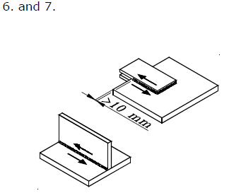 |
6.Continuous fillet welds transmitting a shear flow, such as web to flange welds in plate girders. For continuous full penetration butt weld in shear use Category C2. 7. Fillet welded lap joint. |
6.— Stress range to be calculated from the weld throat area. 7. — Stress range to be calculated from the weld throat area considering the total length of the weld. — Weld terminations more than 10 mm from the plate edge. |
Non-butt welds E (or F):
For non-welded material but with welded attachments, the influence of the weld is taken into account as well.
For stresses perpendicular to the weld – category E:
| Detail category | Constructional details | Description | Requirement |
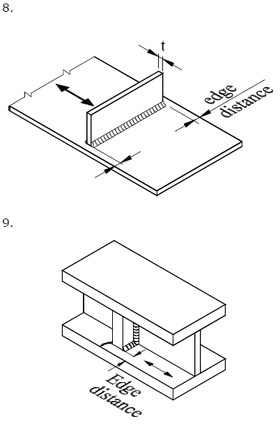 |
8.Transverse attachments with edge distance ≥10 mm 9. Vertical stiffener welded to a beam or a plate girder. 10. Diaphragms of box girders welded to the flange or web |
9.— The stress range should be calculated using principal stresses or the procedure described in [4.3.4] if the stiffener terminates in the web. 8., 9. and 10. The detail category is given for: — Edge distance ≥10 mm — For edge distance < 10 mm the detail category shall be downgraded with one S-N-curve |
|
| E | t ≤25 mm | ||
| F | t > 25 mm | ||
For Joint welds and load-carrying – category E, for full penetration welds, fillet welds – W3:
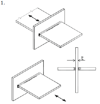 |
1. Full penetration butt welded cruciform joint |
1.:— Inspected and found free from significant defects. The detail category is given for: — Edge distance ≥10mm — For edge distance < 10mm the detail category shall be downgraded with one S-N-curve |
|
| Et ≤25 m | |||
| Ft > 25
mm |
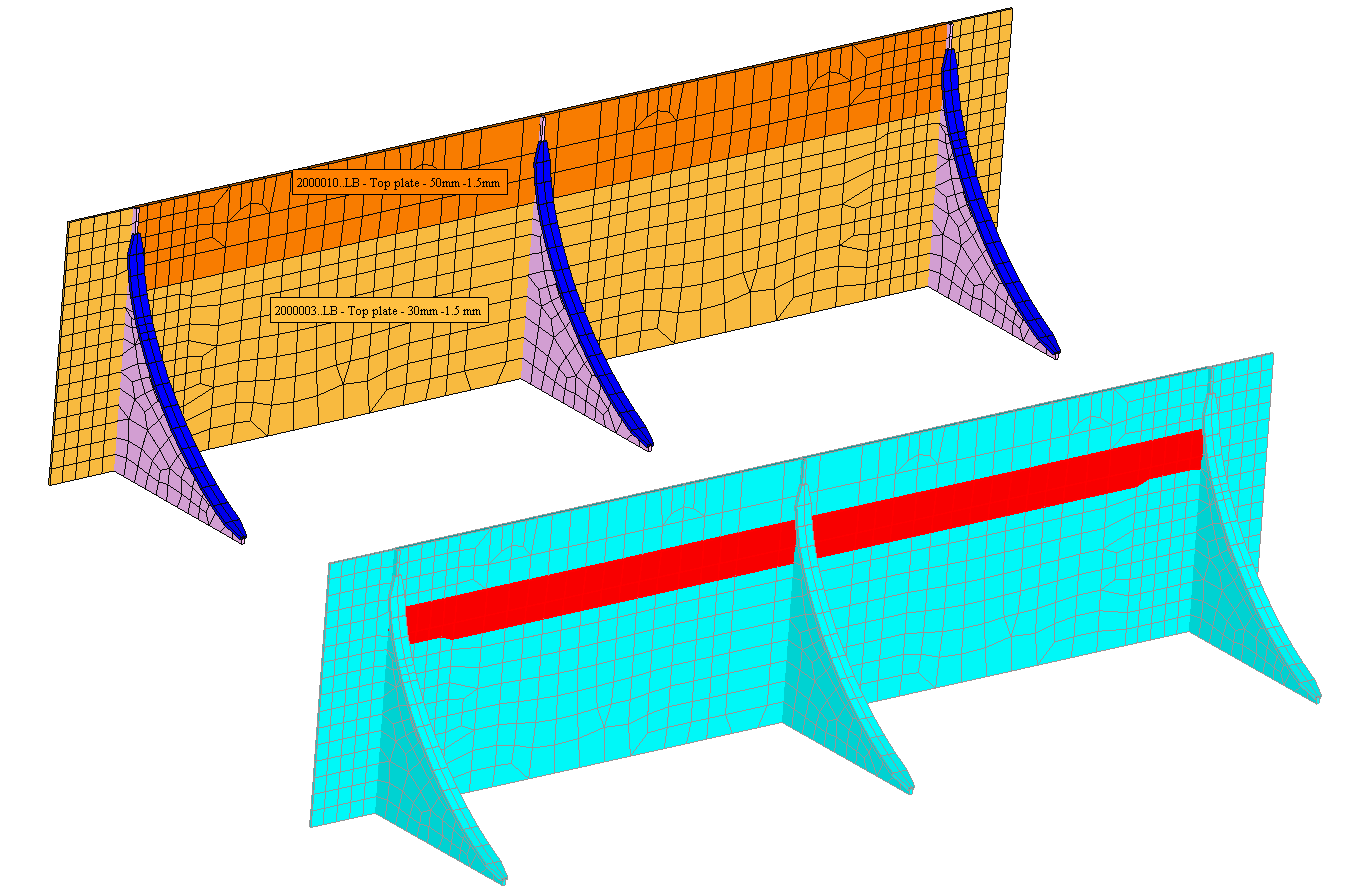
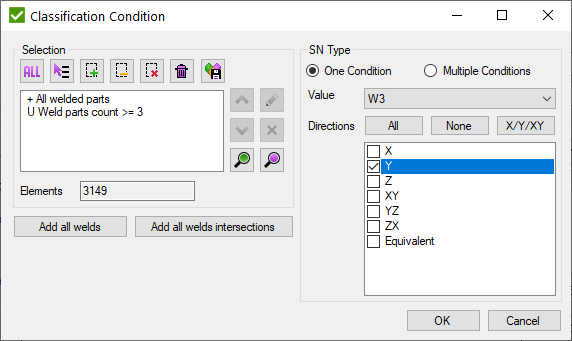
Non Butt welds can be selected by taking common elements from welded elements and welds with 3 connected parts:
Classification in SDC Verifier:
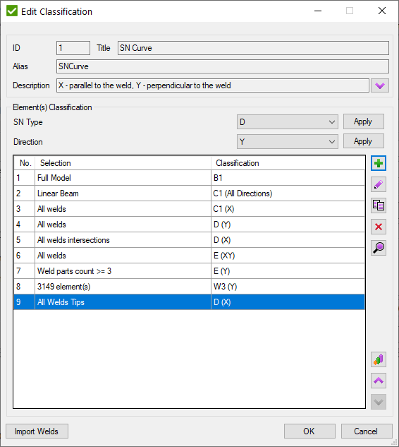
In Classification tool it is possible to assign S-N curve for different selections and in different stress directions in a simple classification table:
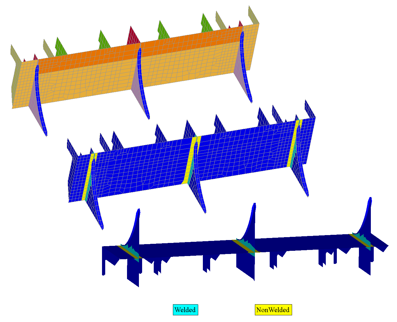
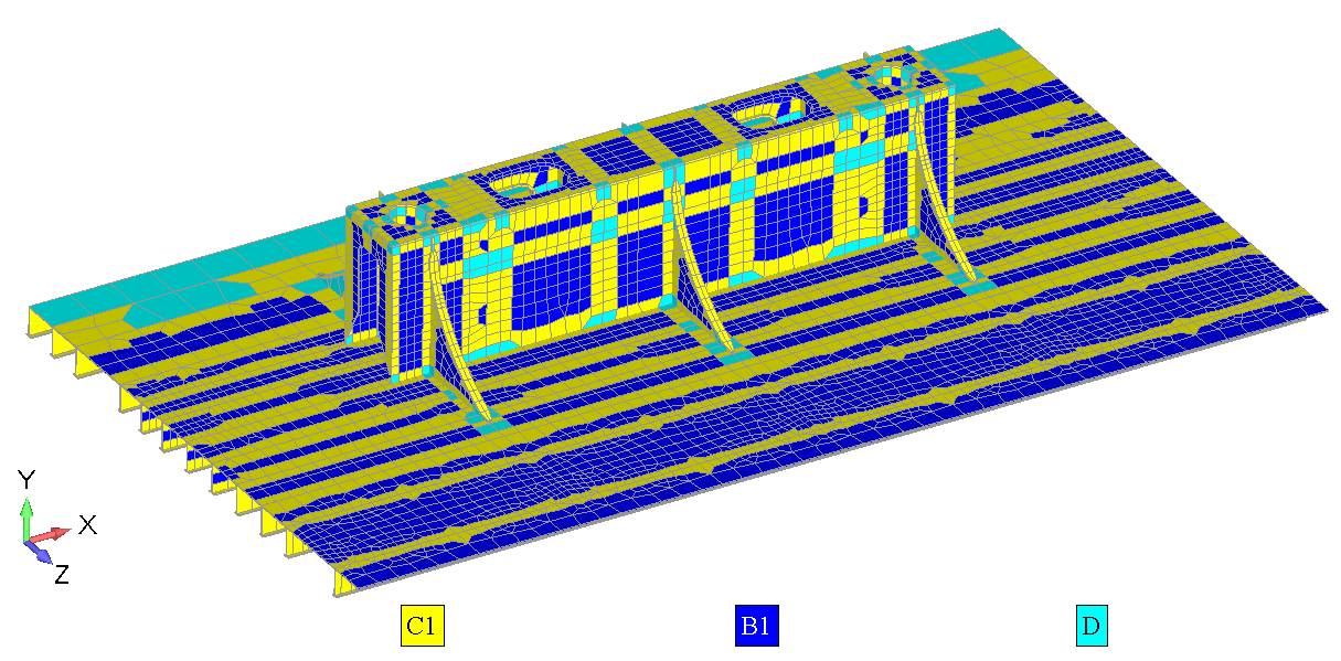
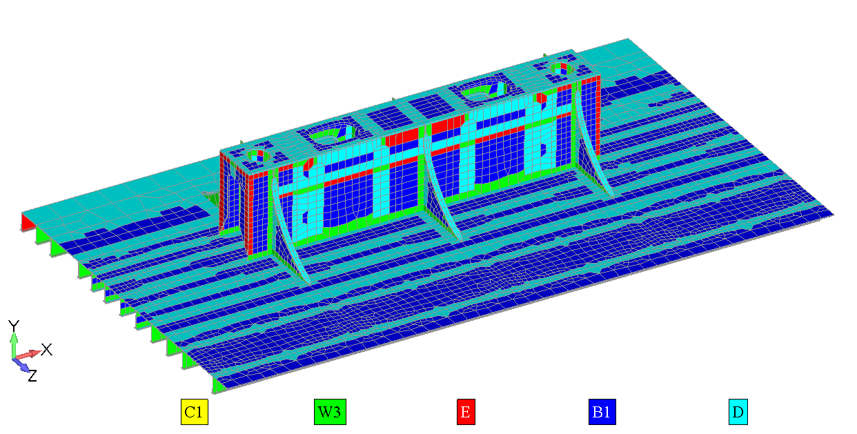
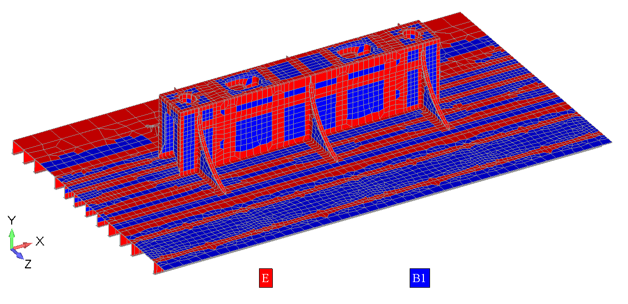
To verify the classification, the colored label plot should be displayed.
Classification in X-direction (parallel to the weld):
Classification in the Y direction (perpendicular to the weld):
Classification in the XY direction:
Fatigue checks according to the DNV RP C203 can be performed in SDC Verifier. Automatic recognition of welds, conversion of results and classification tool help to speed the verification.
