Midsurface Modeling: Simplifying Complex 3D Geometry for Faster FEA
Manual midsurface extraction in finite element analysis (FEA) can be tedious, error-prone, and time-consuming — especially for complex geometries or large assemblies. Engineers need a solution that streamlines geometry preparation without sacrificing accuracy.
SDC Verifier automates midsurface generation, converting complex 3D solid models into clean, analysis-ready midsurfaces in minutes. This automation eliminates manual errors, reduces preprocessing time, and delivers high-quality results.
Manual Midsurface Extraction Wastes Time
For thin-walled structures like plates, shells, or sheet metal parts, simplifying 3D models into midsurfaces is critical to optimize meshing and computational efficiency.
However, the manual process introduces major challenges:
- Time-Consuming: Creating midsurfaces manually requires extensive effort.
- Error-Prone: Inconsistent thickness representation and connectivity issues can lead to inaccurate FEA results.
- Complex Geometries: Overlapping surfaces, holes, and fillets make manual midsurface extraction impractical.
Insight from Practice:
Engineers often face delays in project timelines due to these bottlenecks. For example, extracting midsurfaces for large-scale assemblies can take days without automation, affecting downstream processes like meshing and solver setup.
SDC Verifier streamlines midsurface modeling with automation tools designed to handle complex 3D-to-2D conversion in a few steps.
Watch the process in action:
Step-by-Step Process Using SDC Verifier
1. Import the Geometry
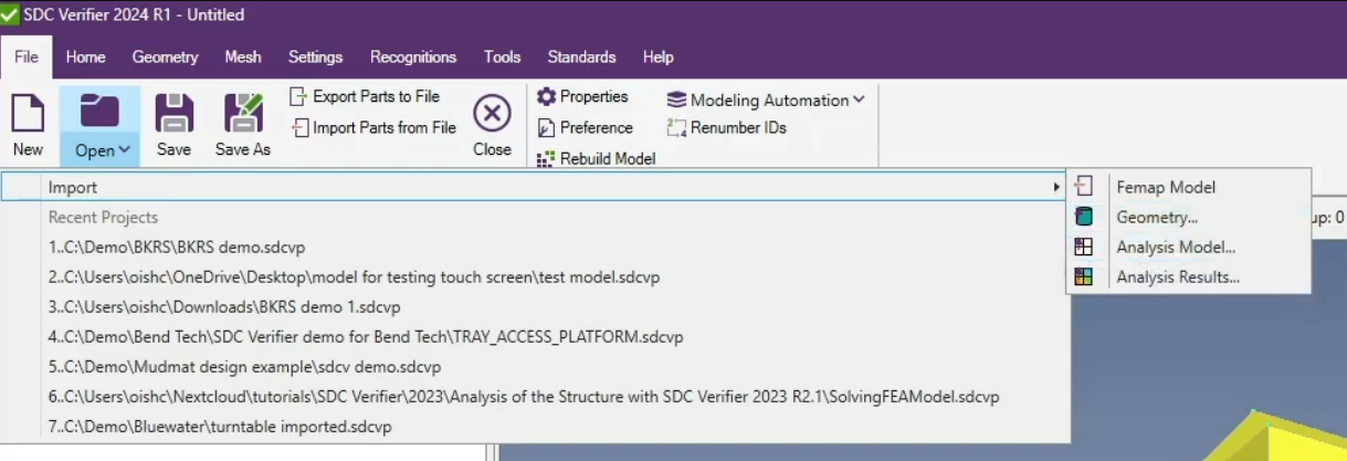
Start by importing the 3D geometry file (e.g., STEP) into SDC Verifier.
- Automated Geometry Recognition: SDC Verifier identifies solid models and prepares them for midsurface extraction.
- Supported Formats: STEP and other standard geometry types are compatible.
2. Simplify the Geometry
Before midsurface generation, use Cleanup and Feature Suppression tools to simplify the model by removing unnecessary features:
- Feature Suppression: Automatically eliminates minor holes, fillets, and notches that add no value to FEA.
- Cleanup: Detects and removes unattached surfaces or redundant geometry fragments.
This step ensures the geometry is clean, reducing the element count and avoiding solver errors.
Pro Tip: Focus on retaining only critical features that influence structural performance for thin-walled models.
Traditional manual extraction involves guesswork and inconsistencies. SDC Verifier automates this step, ensuring structural fidelity even for intricate or large-scale models.
3. Generate Midsurfaces Automatically
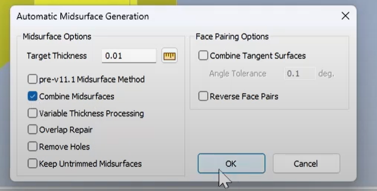
Using the Automatic Midsurface tool, engineers can extract midsurfaces quickly and accurately.
- Automatic Thickness Detection: SDC Verifier automatically detects plate thickness directly from solid geometry.
- Tolerance Adjustment: Define allowable tolerances for midsurface creation and seamlessly combine multiple midsurfaces into unified parts.
Clarified Workflow: The midsurface geometry is created after simplification, ensuring a cleaner and more accurate result.
4. Ensure Connectivity (Optional Step)
In most cases, SDC Verifier’s automatic midsurface tools resolve gaps and overlaps seamlessly. However, for manual refinement:
- Extend Tool: Automatically lengthens midsurfaces to adjacent surfaces, aligning edges precisely.
- Intersect Tool: Creates intersection curves for overlapping surfaces to ensure alignment.
Note: The Extend function automatically lengthens midsurfaces to adjacent perpendicular surfaces, ensuring proper alignment and eliminating gaps. The Intersect tool creates precise curves at the points where the surfaces of two solids intersect, simplifying the division of solid geometry and forming clean boundaries for midsurface extraction.
- Free Edge Tool: Highlights disconnections visually for quick fixes, reducing manual guesswork.
This is a very vital functions automatically identifies free edges between shell elements and highlights them with different colors. This visual aid allows engineers to quickly detect and resolve connectivity issues, ensuring seamless midsurface integration and preventing unintended gaps in the mesh.
Clarification: This step addresses manual corrections where needed. For clean geometries, it’s often unnecessary after automatic generation.
5. Generate the Mesh
Finally, apply mesh attributes to the midsurfaces and generate clean, high-quality meshes:
- Mesh Surface Tool: Define mesh parameters, including size, shape (e.g., quadrilateral elements), and distribution.
- Automated Meshing: The result is a uniform, analysis-ready mesh optimized for solver performance.
Automating the meshing process reduces preprocessing errors and ensures FEA-ready results.
The Result: Faster Preprocessing and High-Quality FEA Models
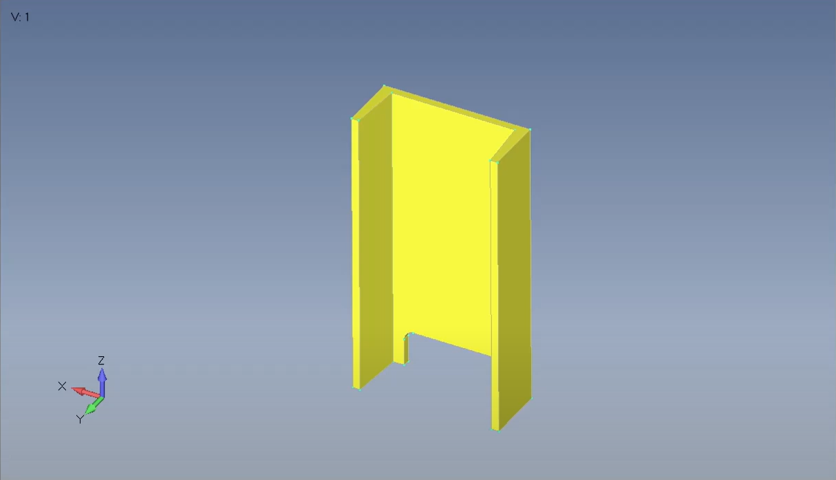
By automating midsurface extraction, SDC Verifier delivers:
✅ Up to reduction in preprocessing time compared to manual methods.
✅ Accurate thickness representation for structural fidelity.
✅ Clean, connected midsurfaces ready for analysis.
 |
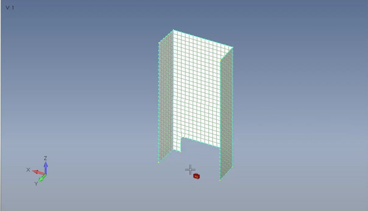 |
Lower element counts and optimized surfaces enable engineers to analyze large assemblies efficiently without overloading computational resources.
Manual vs. Automated Midsurface Extraction:
| Aspect | Manual Approach | Automated Approach with SDC Verifier |
|
Time Efficiency |
Labor-intensive; significant time investment. |
Rapid extraction in a fraction of the time. |
|
Accuracy |
Prone to human error, especially for complex geometries. |
High consistency; reduces errors through automation. |
|
Geometry Complexity |
Requires detailed manual input for intricate surfaces. |
Handles intricate surfaces seamlessly with tools like Automatic Midsurface |
|
Thickness Assignment |
Requires manual property mapping to shell elements. |
Automatically maps properties using Assign Mesh Attributes. |
|
Suitability |
Feasible for simple geometries or small models. |
Ideal for large-scale and complex assemblies. |
Table 1. Manual vs. Automated Midsurface Extraction
Practical Challenges in Midsurface Modeling
Handling intricate geometry is a crucial challenge in midsurface modeling, especially for components with complex intersections, fillets, and transitions. Ensuring that midsurfaces accurately represent these areas while maintaining connectivity across the model is critical to producing reliable simulation results.
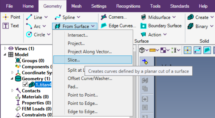
The Intersect tool in SDC Verifier creates precise curves at the points where the surfaces of two solids intersect, simplifying the division of solid geometry and forming clean boundaries for midsurface extraction. These intersection curves are critical for ensuring accurate segmentation and connectivity in complex assemblies.
To streamline midsurfacing, solid geometry should be properly connected into welded or casted structural members using the Add command. This allows automatic midsurface generation and seamless extension of plates into one unified part, reducing manual adjustments.
Poor mesh quality, such as distorted elements or inconsistent connectivity, often originates from improper cleanup or midsurfacing. Incomplete removal of unnecessary features, irregular geometry, or abrupt transitions during the cleanup phase can introduce complexities that propagate into the mesh, compromising midsurface accuracy and simulation results.
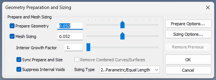
SDC Verifier’s Prepare Geometry tool addresses these challenges by automating the identification and resolution of geometric conditions that could lead to suboptimal meshing.
This tool performs:
- Curve and Surface Segmentation: Automatically adjusts curves and surfaces to ensure a uniform element distribution during meshing.
- Feature Suppression: Removes minor geometric features such as fillets, holes, and notches that are not critical to the analysis, simplifying the midsurface without affecting structural fidelity.
- Combined Curves and Boundary Surfaces: Generates optimized curves and surfaces for cleaner, more robust mesh generation.
Common Pitfalls and How to Avoid Them:
| Pitfall | Challenge | SDC Verifier Tool/Feature | Solution |
|
Mesh Discontinuity |
Gaps between midsurface regions disrupt load paths and accuracy. |
Extend, Intersect and NonManifold Add |
Ensures proper alignment and connectivity between adjacent midsurfaces. |
|
Distorted Mesh Elements |
Poor element shapes lead to stress artifacts and solver errors. |
Prepare Geometry and Feature Suppression |
Removes unnecessary features and optimizes meshing surfaces. |
|
Incorrect Thickness |
Inaccurate or inconsistent property assignments. |
Assign Mesh Attributes |
Automatically maps thickness directly from the 3D model to shell elements. |
|
Overly Complex Geometry |
Unnecessary details increase element count and computational demand. |
Cleanup |
Eliminates minor or unattached surface fragments to simplify the geometry. |
Table 2: Common Pitfalls and SDC Verifier Solutions
These features ensure seamless connections across midsurface models, preventing issues such as mesh gaps or misaligned nodes, which could compromise simulation accuracy.
Conclusion
Manual midsurface extraction is inefficient and error-prone. SDC Verifier automates the process, enabling engineers to quickly convert complex 3D geometries into clean, connected midsurfaces optimized for FEA.
