Implementing EN 1993-1-8 (2005) Bolt Check in SDC Verifier
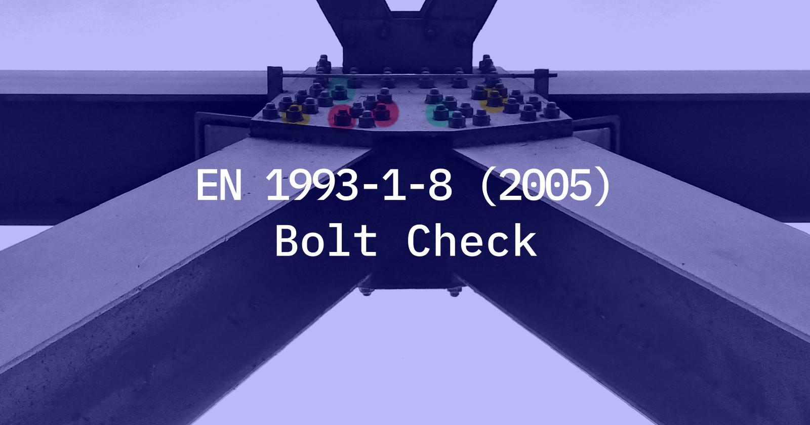
Bolted joint analysis is vital in structural engineering as it ensures the safe and efficient transfer of loads between structural members.
Bolts play a critical role in joining components together, and their analysis helps to determine the overall stability and strength of the structure. By analysing bolted connections, engineers can assess factors such as shear, tension and bearing capacity to ensure that the connections can withstand anticipated loads and prevent failure or collapse. Accurate bolted connection analysis improves structural integrity, minimises risk and enables optimum design, ultimately ensuring the safety and reliability of the entire structure.
Another great feature of SDC Verifier is described here. Connections made with bolts according to EN 1993-1-8 (2005) Chapter 3 can now be checked with SDC Verifier directly within your standard FEA program.
For the EN 1993-1-8 bolt check the following checks can be performed:
Shear connection
- A. bearing type;
- B. slip-resistance at serviceability;
- C. slip-resistance at ultimate;
Tension connection
- D. non-preloaded;
- E. preloaded.
For shear and tension together
Table 3.2: Categories of bolted connections
| Category | Criteria | Remarks |
|---|---|---|
|
Shear connections |
||
|
A bearing type |
\[F _{\nu,Ed} \leq F _{\nu,Rd} \]; \[F _{\nu,Ed} \leq F _{b,Rd} \] | No preloading required. Bolt classes from 4.6 to 10.9 may be used |
|
B slip-resistant at serviceability |
\[F _{\nu,Ed,ser} \leq F _{\nu,Rd,ser} \]; \[F _{\nu,Ed} \leq F _{\nu,Rd} \]; \[F _{\nu,Ed} \leq F _{b,Rd} \] | Preloaded 8.8 or 10.9 bolts should be used. For slip resistance at serviceability see 3.9. |
|
C slip-resistant at ultimate |
\[F _{\nu,Ed} \leq F _{s,Rd} \]; \[F _{\nu,Ed} \leq F _{b,Rd} \]; \[|AC_{2} \sum{F_{\nu,Ed}} \leq N_{net,Rd} AC_{2}|\] | Preloaded 8.8 or 10.9 bolts should be used. For slip resistance at ultimate see 3.9.\[N_{net,Rd}\] see 3.4.1(1) c) |
| Tension Connections | ||
| D
non-preloaded |
\[F _{t,Ed} \leq F _{t,Rd} \]; \[F _{t,Ed} \leq B _{p,Rd} \] | No preloading required. Bolt classes from 4.6 to 10.9 may be used.\[ B _{p,Rd} \] see Table 3.4 |
|
E preloaded |
\[F _{t,Ed} \leq F _{t,Rd} \]; \[F _{t,Ed} \leq B _{p,Rd} \] | Preloaded 8.8 or 10.9 bolts should be used. \[ B _{p,Rd} \] see Table 3.4 |
| The design tensile force Ft,Ed. should include any force due to prying action, see 3.11. Bolts subjected to both shear force and tensile force should also satisfy the criteria given in Table 3.4. | ||
Axial and Shear Forces are automatically extracted from the FEA model (Ansys, FEMAP or Simcenter 3D /NX CAE) by SDC Verifier, the bolt diameter is taken by default from the property but the user has off course the possibility to override this.
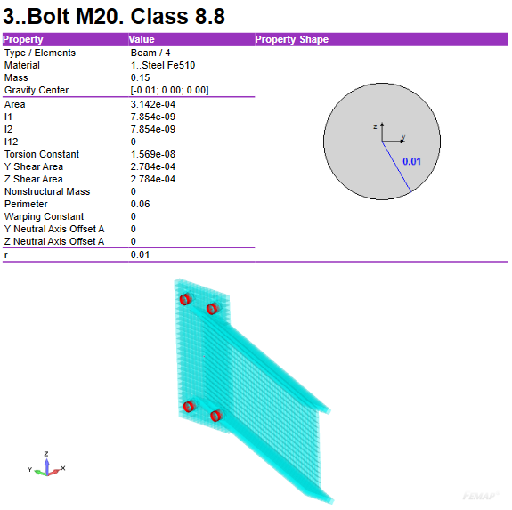
In the following example a check on the M20 bolts, Class 8.8 is shown. The properties and locations of the bolt is taken from the model setup report (an automatic generated report with a complete description of the FEA model):
The nominal values of the yield strength f_yb and the ultimate tensile strength f_ub for bolts are taken from the table after selection of the bolt class of the element:
Table 3.1: Nominal values of the yield strength fyb and the ultimate tensile strength fub for bolts
| Bolt class | 4.6 | 4.8 | 5.6 | 5.8 | 6.8 | 8.8 | 10.9 |
|---|---|---|---|---|---|---|---|
| fyb(N/mm2) | 240 | 320 | 300 | 400 | 480 | 640 | 900 |
| fub(N/mm2) | 400 | 400 | 500 | 500 | 600 | 800 | 1000 |
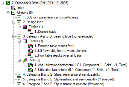
In the following example the bolt connection is checked without controlled preloading or pretension, but this can be selected as well by selection the relevant check category, see below:
Picture of Eurocode 3 Bolt menu with the tables and plots used in this article
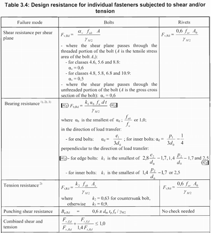
The table below includes formulas for design resistance calculation used in the SDC check.
Because controlled preloading is not applied the bolts in the example will be checked according to the limits of category A: bearing type and for the shear loading the category D non-preloaded of Table 3.2 is used.
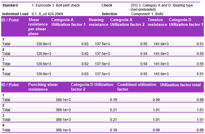
Detailed results of the bolts checking according to EN 1993-1-8 (2005) is shown in the table.
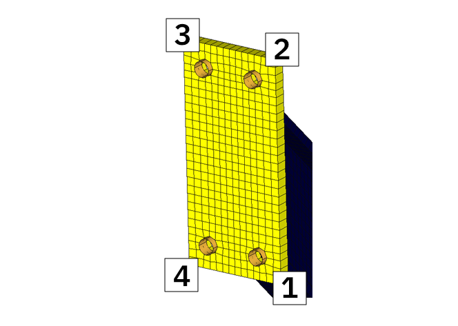
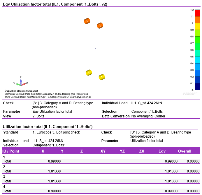
The Bolts IDs (=the element numbers of the bolt elements):
The table below shows the worst results on the bolt selection. IDs of the bolts with worst results shown in the table.
The total utilization factor shows the maximum results of the checks on both shear and axial loading of the bolt (=last column of the previous table)
With the help of the calculation core of SDC Verifier this check can be repeated for different load situations. In the example below 5 more load situations and a load group are created. The load sets below consist of a factor times a unit force. (for the ease of the explanation the unit force results in 0.71 N axial load and 0.71 shear load in each bolt)
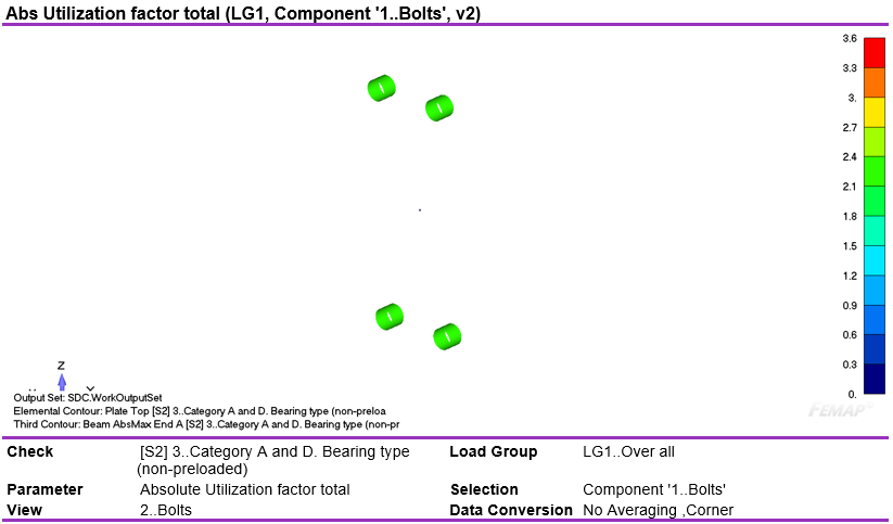
All load combinations combined into the load group
By showing the load group result, the maximum load situation of every bolt is reported by plotting the maximum utilization of the bolt check for all the load situations in the load group:
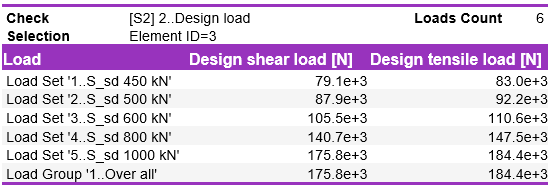
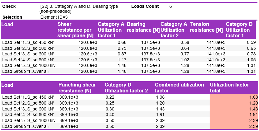
The table below shows design load (axial and shear force) on the bolt ID 3 over loads. The last row of the table shows results for the Load group, in this case, is equal to the worst load set 5.
Table with detailed results over loads for bolt ID 3 are shown in the table below.
This is another example how to speed up verification of FEA results according to standards, rules and regulations. With help of SDC Verifier it is very easy to perform bolt check according to EN 1993-1-8 (2005), all checks are directly done within the FEA model and the results can be included in the generated overall result report.
No more tedious procedures of selecting the bolt elements, exporting the bolt results for all different load situations to a spreadsheet program, setting up a bolt check and summarizing all results in the spreadsheet mode and updating this procedure after each design update.
Interested to see how the FEA result report of this small example looks? Download the pdf-version of the result report here
Do you want to try this yourself in ANSYS, FEMAP or Simcenter 3D /NX CAE? Ask for a trial here.


