Understanding FEA: Solving Engineering Problems with Finite Element Analysis

Finite Element Analysis (FEA) is a computational technique used by engineers to predict how structures or components will respond to various physical forces, including stress, heat, and vibration. By breaking down complex structures into smaller, manageable elements, FEA uses mathematical models to simulate real-world behavior across different scenarios.
This approach allows engineers to assess design performance, ensure safety, and optimize efficiency without relying on costly or time-consuming physical prototypes. Essential in industries such as aerospace, automotive, and civil engineering, FEA plays a vital role in modern engineering, ensuring that designs meet rigorous safety and performance standards before they are brought to life.
A short history of FEA
Euler made the first steps in solving systems of differential equations in the 18-the century. Alexander Hrennikoff and Richard Courant in the 1940s were the first to investigate mechanical problems solving with the help of these methods.
The FEM starts with “Stiffness and Deflection Analysis of Complex Structures,” published in 1956 by Turner, Clough, Martin, and Topp. The term “finite element” was coined by Ray Clough in 1960 at the ASCE Conference on Electronic Computation in Pittsburgh.

What is FEA: Partial Differential Equations
We can describe nearly everything around us with differential equations in partial differentials. Ordinary (with one argument) and partial (with several arguments) differential equations are used very often. An ordinary differential equation is a case of a partial differential equation, but the behavior of solutions is quite different in general.
Equation F (x, y(x), y′(x), . . . , y(n)) = 0 is an ordinary differential equation of n-th order for the unknown function y(x), where F is given.
Key Applications of FEA
When thinking “what is FEA”, consider how and where it is usually applied. With the help of FEA, engineers can immediately increase material accuracy when designing a product, seeing how all physical stresses may affect the design. They also can determine how stresses within one piece will affect the materials in another separate part.
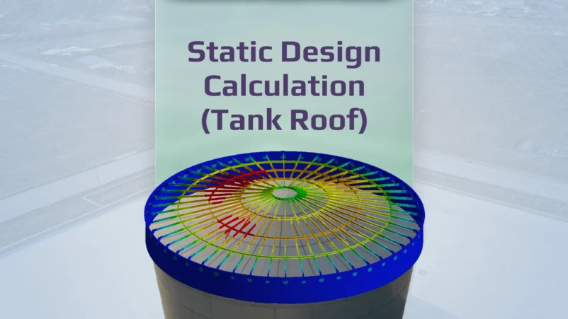
A key advantage of FEA is its ability to model how critical factors, like stress, affect an entire structure and reveal potential failure points. Stress scenarios can be accurately simulated, allowing engineers to pinpoint weaknesses and optimize designs.
Techniques like FEA, Computational Fluid Dynamics (CFD), and Multibody Dynamics (MBD) help predict stress distributions and deformations in complex assemblies. The FEA is usually used in:
- Automotive Industry: FEA is integral to the automotive industry, allowing engineers to test vehicle components for durability and safety. Simulations of impacts, fatigue, and thermal effects enable engineers to design everything from car frames to battery casings with optimal performance and safety in mind, ensuring that vehicles are safe and reliable under various conditions.
- Civil Engineering: In civil engineering, FEA is applied to evaluate the safety and stability of large structures. Engineers use FEA to identify areas of high stress, understand how these structures will hold up over time, and optimize designs to meet stringent safety standards.
- Aerospace Industry: FEA helps in testing how aircraft components perform under extreme conditions. Engineers simulate factors like aerodynamics, vibrations, and heat resistance to ensure that each part meets safety and performance requirements.
So, for what is FEA paramount in modern engineering? It empowers engineers to simulate and evaluate the performance of designs before physical prototypes are built, thereby reducing costs, time, and risks associated with product development. FEA assists in optimizing designs, identifying potential weaknesses, and ensuring that engineering solutions meet safety, performance, and regulatory standards.
FEA terminology

A comprehensive understanding of FEA terminology is essential for practitioners. It forms the language through which engineers communicate and interpret analysis results. FEA terminology provides the framework for accurate analysis and effective collaboration among multidisciplinary teams, from boundary conditions and meshing techniques to material properties and convergence criteria. By mastering FEA terminology, engineers can effectively interpret simulation results, troubleshoot issues, and make informed decisions to improve the performance and reliability of engineering designs.
In FEA, the researched structure is divided into separate parts – finite elements connected into nodes. These nodes are then connected by mathematical equations called shape functions. Together with the element type, the applicable material properties, and geometric characteristics, these nodes and shape functions describe what is generally called a finite element. There are many different types of elements used in FEA. These elements are developed independently and vary from one finite element (FE) software to another. In general, there are three groups of elements which are one-dimensional (1D), two-dimensional (2D), and three-dimensional (3D) elements. Each finite element characterizes by:
- a number of dimensions of the space used (1-D, 2-D, 3-D);
- geometric shape, usually being a simple geometric figure (right line section, triangle, square, tetrahedron);
- nodes set situated usually, but not always at lines or surfaces of elements chapter, being typical for neighboring elements;
- a set of degrees of freedom used, relating more often to nodes (but not obligatory to nodes) – displacements, bends, etc.
- rules, defining the relationship between finite element nodes’ displacements and system nodes. For instance, element nodes can be attached to system nodes rigidly or with joints;
- the system of approximation functions, defined inside the finite element area and letting roughly express the displacements components in any point of the element through its degrees of freedom;
- physical law defining the relationship between internal effort and displacements;
- the class of tasks to which a given type of finite element is applicable;
- the set of allowed loads and effects that can be applied directly to the finite element and the way of their setting. The collection of interconnected and basement-attached finite elements forms a design diagram called finite elements diagram or finite element model;
- and last but not least – the list of limitations and usage recommendations.
FEA Software Options
Different types of software are used to simulate other engineering and physical situations. The most complicated task in performing a plate buckling check for a large structure, like a complete ship design, on a general Finite Element Analysis model is to define numerous plates and the dimensions of these plates to be verified. To guarantee the correct results, the model has to have a fine mesh with small enough finite elements.
With the help of a specific tool, it is possible to break the boundaries of general FEA Analysis and enable the code checking directly in Simcenter 3D, Femap, Ansys, SDC Verifier. The recognition of plates, stiffeners, and girders is based on mesh connectivity and can be performed on any structure which is built with 2D or, in some cases, even 3D elements. The structural members are defined automatically and mesh independently.
Since checks are done on structural items and not on finite elements, the best solution for both execution time and accuracy of the results would be to use the extension for general FEA programs capable of the automatic recognition of the structural members mesh independently.
- ANSYS is one of the most used finite element analysis software. It has lots of kinds of tools to simulate different engineering and physical situations, such as fluids in CFX and Fluent, static and dynamic motion analyses, steady-state and transient thermal and structural analyses, and modal analyses.
- SDC Verifier speeds up the design phase by storing the full calculation process. A recalculation after a modification requires just a single click. All calculation settings are reapplied to the new model and FEM results. The Code of the checks is completely open, so you can modify the formulas of a standard or write your own custom rules.
- Most engineers related to software have worked with Autodesk Inc. from their CAD software such as Autocad and Inventor.
- Nastran is one of the most iconic finite element analysis software that was created by NASA. Nastran’s source codes are available in various kinds of other software such as NX Nastran, MSC Nastran, etc.
Simcenter Femap is an advanced simulation application for creating, editing and inspecting finite element models of complex products or systems. You can use advanced workflows in Simcenter Femap to model components, assemblies, or systems, to then determine a model’s behavioral response when subjected to real-world conditions.
There are also a lot of other types of FEA software for any type of task.
SDC Verifier speeds up the design phase by storing the full calculation process. A recalculation after a modification requires just a single click. All calculation settings are reapplied to the new model and FEM results. The Code of the checks is completely open, so you can modify the formulas of a standard or write your own custom rules.
SDC Verifier seamlessly addresses challenges in FEA by offering advanced design, verification, and validation tools, customizable checks and templates, specialized modules for fatigue analysis, seamless solving and integration with leading FEA software, and a user-friendly interface. By empowering engineers with these capabilities, SDC Verifier enhances the efficiency, accuracy, and reliability of finite element analysis processes, ultimately enabling better-informed design decisions and optimized product performance.
Conclusion
Summing everything up, what is FEA? FEA is a powerful engineering tool that enables precise simulations of how structures respond to various physical forces. Through FEA, engineers can analyze and improve designs without the need for costly physical prototypes. It saves time and resources. Widely used across industries like automotive, aerospace, and civil engineering, FEA helps ensure that products meet critical safety and performance standards.


