Example F.11C – Single-Angle Flexural Member with Vertical and Horizontal Loading
This benchmark reproduces the calculations and evaluation process from Example F.11C – Single-Angle Flexural Member with Vertical and Horizontal Loading in the AISC Design Examples manual. Using SDC Verifier 2025 R1, we model the same geometry, loading conditions, and material assumptions to verify alignment between automated results and the manual benchmark.
The study includes uniform vertical dead and live loads along with a horizontal wind load, acting on a simply supported angle braced only at the ends. Both LRFD and ASD design methodologies are evaluated according to ASCE/SEI 7 load combinations, with the material defined as ASTM A36.
This benchmark serves to:
-
Validate SDC Verifier’s limit state checks against AISC manual results.
-
Highlight differences due to FEA modeling simplifications (e.g. fillet radii).
-
Confirm governing flexural limit states across both major and minor principal axes.
Task
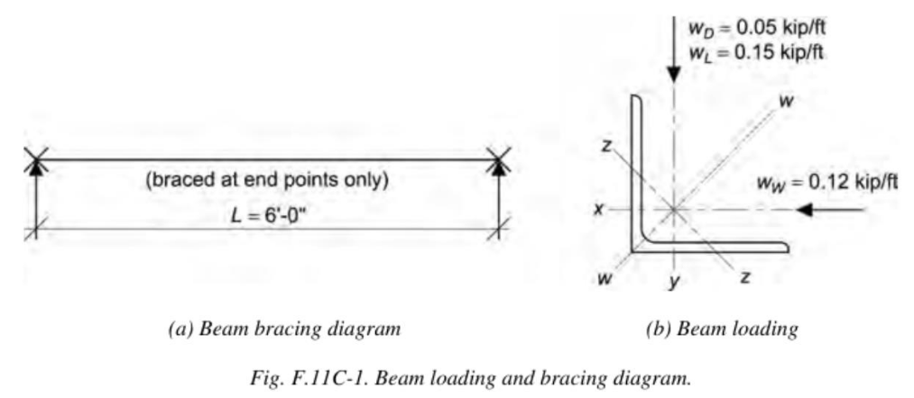
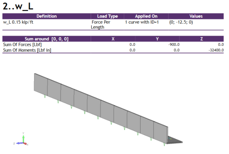
Directly applying the requirements of the AISC Specification, select a single angle for span and uniform vertical dead and live loads as shown in Figure F.11C-1. The horizontal load is a uniform wind load. There is no deflection limit for this angle. The angle is simply supported and braced at the end points only and there is no lateral-torsional restraint.
Use:
- Load combination 4 from Section 2.3.1 of ASCE/SEI 7 for LRFD
- Load combination 6 from Section 2.4.1 of ASCE/SEI 7 for ASD
The angle is ASTM A36 material.
Loading and Bracing Diagram (Fig. F.11C-1)
(a) Beam Bracing Diagram:
- Braced at end points only
- Span: (L = 6′ – 0″)
(b) Beam Loading:
- Dead Load: ( wD = 0.05, kip/ft (vertical)
- Live Load: ( wL = 0.15, kip/ft (vertical)
- Wind Load: ( wW = 0.12, kip/ft (horizontal)
Solution
From AISC Manual Table 2-4, the material properties are:
- ASTM A36
Fy = 36, ksi
Fu = 58, ksi
From Chapter 2 of ASCE/SEI 7, the required flexural strength is:
- LRFD
wux = 1.2 × 0.05 kip/ft + 0.15 kip/ft = 0.210 kip/ft
wuy = 1.0 × 0.12 kip/ft = 0.120 kip/ft
Mux = (wux × L2) / 8
= (0.210 kip/ft × (6 ft)2) / 8
= 0.945 kip-ft
Muy = (wuy × L2) / 8
= (0.120 kip/ft × (6 ft)2) / 8
= 0.540 kip-ft
- ASD
wax = 0.05 kip/ft + 0.75 × 0.15 kip/ft = 0.163 kip/ft
way = 0.75 × (0.6 × 0.12 kip/ft) = 0.0540 kip/ft
Max = (wax × L2) / 8
= (0.163 kip/ft × (6 ft)2) / 8
= 0.734 kip-ft
May = (way × L2) / 8
= (0.0540 kip/ft × (6 ft)2) / 8
= 0.243 kip-ft
Try a L4×4×¼.
Sign Convention for Geometric Axes Moments
- LRFD
Mux = −0.945 kip-ft
Muy = 0.540 kip-ft
- ASD
Max = −0.734 kip-ft
May = 0.243 kip-ft
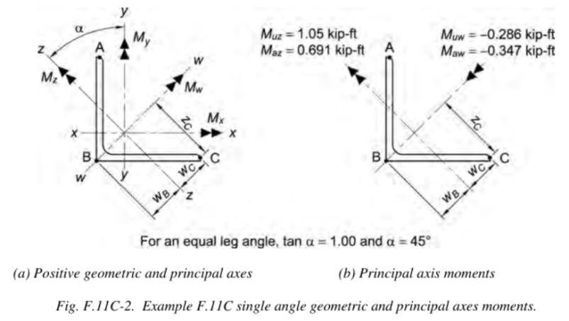
Principal Axes Moments (from Figure F.11C-2)
- LRFD
Muw = Mux cos α + Muy sin α
= (−0.945 kip-ft)(cos 45°) + (0.540 kip-ft)(sin 45°)
= −0.286 kip-ft
Muz = −Mux sin α + Muy cos α
= −(−0.945 kip-ft)(sin 45°) + (0.540 kip-ft)(cos 45°)
= 1.05 kip-ft
- ASD
Maw = Max cos α + May sin α
= (−0.734 kip-ft)(cos 45°) + (0.243 kip-ft)(sin 45°)
= −0.347 kip-ft
Maz = −Max sin α + May cos α
= −(−0.734 kip-ft)(sin 45°) + (0.243 kip-ft)(cos 45°)
= 0.691 kip-ft
Geometric Properties (From AISC Manual Table 1-7)
L4×4×¼
A = 1.93 in.2
Sx = Sy = 1.03 in.3
Ix = Iy = 3.00 in.4
Iz = 1.19 in.4
rz = 0.783 in.
Principal Axes Properties (From AISC Shapes Database)
wB = 1.53 in.
wC = 1.39 in.
zC = 2.74 in.
Iw = 4.82 in.4
SB = 0.778 in.3
SC = 0.856 in.3
SwC = 1.76 in.3
Z-Axis Nominal Flexural Strength
Note:
Muz and Maz are positive; therefore, the toes of the angle are in compression.
Flexural Yielding
From AISC Specification Section F10.1, the nominal flexural strength due to the limit state of flexural yielding is:
Mnz = 1.5 My (from Spec. Eq. F10-1)
= 1.5 Fy SzB
= 1.5 × (36 ksi) × (0.778 in.3)
= 42.0 kip-in.
Lateral-Torsional Buckling
From the User Note in AISC Specification Section F10:
The limit state of lateral-torsional buckling does not apply for bending about the minor axis.
Leg Local Buckling
Check slenderness of the outstanding leg in compression:
λ = b / t
= 4.00 in. / ¼ in.
= 16.0
Limiting Width-to-Thickness Ratios
From AISC Specification Table B4.1b, Case 12:
λp = 0.54 √(E / Fy)
= 0.54 √(29,000 ksi / 36 ksi)
= 15.3
λr = 0.91 √(E / Fy)
= 0.91 √(29,000 ksi / 36 ksi)
= 25.8
Flexural Yielding (Noncompact Leg)
Because
λp < λ < λr,
the leg is noncompact in flexure.
Sc = SzC (to toe in compression)
= 0.856 in.3
Mnz = Fy Sc [2.43 – 1.72 (b/t) √(Fy/E)] (Spec. Eq. F10-6)
= (36 ksi)(0.856 in.3) × [2.43 – 1.72(16.0) √(36 ksi / 29,000 ksi)]
= 45.0 kip-in.
Flexural Yielding Limit State Controls
Mnz = 42.0 kip-in. or 3.50 kip-ft
Z-Axis Available Flexural Strength
From AISC Specification Section F1:
- LRFD
ϕb = 0.90
ϕbMnz = 0.90 × 3.50 kip-ft = 3.15 kip-ft
- ASD
Ωb = 1.67
Mnz / Ωb = 3.50 kip-ft / 1.67 = 2.10 kip-ft
W-Axis Nominal Flexural Strength
Flexural Yielding
(from Spec. Eq. F10-1)
Mnw = 1.5 My
= 1.5 Fy SwC
= 1.5 × (36 ksi) × (1.76 in.3)
= 95.0 kip-in.
Lateral-Torsional Buckling
Determine Mcr
For bending about the major principal axis of an equal-leg angle without continuous lateral-torsional restraint, use:
AISC Specification Equation F10-4
Cb = 1.14 from Manual Table 3-1
βw = 0 (from AISC Specification Section F10.2(b)(1), for equal leg angles)
Critical Moment Mcr:
Mcr = [9 E A rz t Cb] / [8 Lb] × √{1 + 4.4 (βw rz / Lbf)2 + 4.4 (βw rz / Lbf)}
= 9 × (29,000 ksi) × (1.93 in.2) × (0.783 in.) × (¼ in.) × (1.14)
÷ [8 × (6 ft) × (12 in./ft)]
× √{1 + 4.4 × [0 × (0.783 in.) / ((6 ft)(12 in./ft)(¼ in.))]2 + 4.4 × [0 × (0.783 in.) / ((6 ft)(12 in./ft)(¼ in.))]}
= 195 kip-in.
Yielding Moment for Comparison
My = Fy SwC
= (36 ksi) × (1.76 in.3)
= 63.4 kip-in.
My / Mcr = 63.4 kip-in. / 195 kip-in.
= 0.325 < 1.0, therefore AISC Specification Equation F10-2 is applicable
Mnw = [1.92 – 1.17 √(My / Mcr)] × My ≤ 1.5 My (Spec. Eq. F10-2)
= [1.92 – 1.17 √(63.4 / 195)] × (63.4 kip-in.)
≤ 1.5 × (63.4 kip-in.) = 95.1 kip-in.
= 79.4 kip-in. < 95.1 kip-in.
= 79.4 kip-in.
Leg Local Buckling
From the preceding calculations, the leg is noncompact in flexure
Sc = SwC (to toe in compression)
= 1.76 in.3
Mnw = Fy Sc × [2.43 – 1.72 (b/t) √(Fy / E)] (Spec. Eq. F10-6)
= (36 ksi)(1.76 in.3) × [2.43 – 1.72(16.0) √(36 ksi / 29,000 ksi)]
= 92.5 kip-in.
Lateral-Torsional Buckling Limit State Controls
Mnw = 79.4 kip-in. or 6.62 kip-ft
W-Axis Available Flexural Strength
From AISC Specification Section F1:
- LRFD
ϕb = 0.90
ϕb Mnw = 0.90 × 6.62 kip-ft = 5.96 kip-ft
- ASD
Ωb = 1.67
Mnw / Ωb = 6.62 kip-ft / 1.67 = 3.96 kip-ft
Combined Loading
The moment resultant has components about both principal axes; therefore, the combined stress ratio must be checked using the provisions of AISC Specification Section H2:
| fra / Fca + frbw / Fcbw + frbz / Fcbz | ≤ 1.0 (Spec. Eq. H2-1)
Note:
Rather than convert moments into stresses, it is acceptable to simply use the moments in the interaction equation. The section properties cancel out, so the numerator and denominator match. It’s important to track the signs of the stresses to ensure proper application. Signs help determine tension/compression, but aren’t used directly in the interaction ratios.
Summary of Required vs. Available Flexural Strength
(Based on Figure F.11C-2)
- LRFD
Muw = 0.286 kip-ft
ϕb Mnw = 5.96 kip-ft
Muz = 1.05 kip-ft
ϕb Mnz = 3.15 kip-ft
- ASD
Maw = 0.347 kip-ft
Mnw / Ωb = 3.96 kip-ft
Maz = 0.691 kip-ft
Mnz / Ωb = 2.10 kip-ft
Stress Checks at Critical Points
At point B:
Mw causes no stress, so the stress ratio is 0. Mz causes tension → taken as negative.
- LRFD
0 − (1.05 kip-ft / 3.15 kip-ft) = 0.333 ≤ 1.0 → o.k.
- ASD
0 − (0.691 kip-ft / 2.10 kip-ft) = 0.329 ≤ 1.0 → o.k.
At point C:
Mw causes tension → negative; Mz causes compression → positive.
- LRFD
(−0.286 kip-ft / 5.96 kip-ft) + (1.05 kip-ft / 3.15 kip-ft) = 0.285 ≤ 1.0 → o.k.
- ASD
(−0.347 kip-ft / 3.96 kip-ft) + (0.691 kip-ft / 2.10 kip-ft) = 0.241 ≤ 1.0 → o.k.
At point A:
Mw and Mz both cause compression → positive.
- LRFD
(0.286 kip-ft / 5.96 kip-ft) + (1.05 kip-ft / 3.15 kip-ft) = 0.381 ≤ 1.0 → o.k.
- ASD
(0.347 kip-ft / 3.96 kip-ft) + (0.691 kip-ft / 2.10 kip-ft) = 0.417 ≤ 1.0 → o.k.
Thus, the interaction of stresses at each point is seen to be less than 1.0 and this member is adequate to carry the required load.
Although all three points were checked, it was expected that point A would be the controlling point, because compressive stresses add at this point.
Example from AISC Design Examples
Material Summary
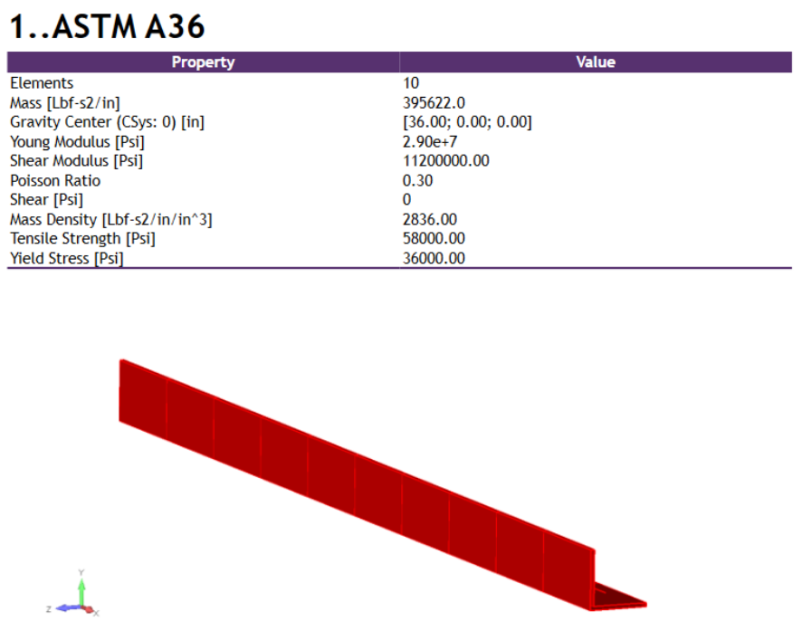
Properties Summary
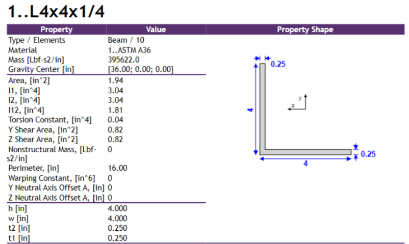
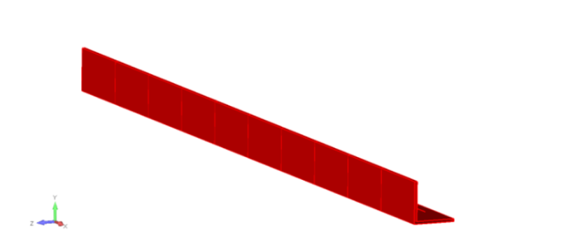
Some slight differences in geometrical properties may be noticed, but these come from the fact that the cross-section is modeled without a root fillet radius and toe radius due to FEA simplifications.
FEM Loads and Constraints

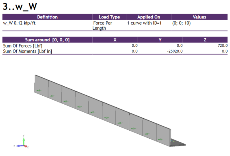
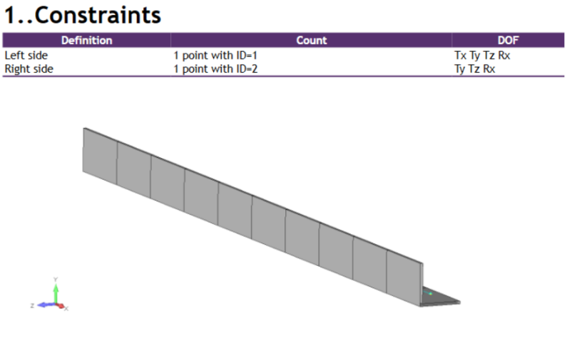
Results

Principal Axes Moments (Figure F.11C-2)
| LRFD | ASD |
|---|---|
| Muw = Mux cos α + Muy sin α = (−0.945 kip-ft)(cos 45°) + (0.540 kip-ft)(sin 45°) = −0.286 kip-ft = 3432 lbf·in | Maw = Max cos α + May sin α = (−0.734 kip-ft)(cos 45°) + (0.243 kip-ft)(sin 45°) = −0.347 kip-ft |
| Muz = −Mux sin α + Muy cos α = −(−0.945 kip-ft)(sin 45°) + (0.540 kip-ft)(cos 45°) = 1.05 kip-ft = 12,600 lbf·in | Maz = −Max sin α + May cos α = −(−0.734 kip-ft)(sin 45°) + (0.243 kip-ft)(cos 45°) = 0.691 kip-ft |
The lateral-torsional buckling limit state controls.
Mnw = 79.4 kip-in. or 6.62 kip-ft = 79,400 lbf·in
The flexural yielding limit state controls.
Mnz = 42.0 kip-in. or 3.50 kip-ft = 42,000 lbf·in
As we can see, the principal axes moment values as well as the available flexural strengths in principal axes coincide with the results from SDC Verifier, the latter being slightly conservative due to the simplified fillet radiuses.
Any of the intermediate results can be checked as well using the calculation details functionality in SDC Verifier, so for example:
Nominal flexural strength according to the limit state of yielding:

Flexural Yielding
(from Spec. Eq. F10-1)
Mnw = 1.5 My
= 1.5 Fy SwC
= 1.5 × (36 ksi) × (1.76 in.3)
= 95.0 kip-in. = 95,000 lbf·in
Nominal Flexural Strength (Leg Local Buckling, Noncompact Leg)
Nominal flexural strength according to the limit state of leg local buckling for sections with noncompact legs:

Leg Local Buckling
(from Spec. Eq. F10-6)
Mnw = Fy Sc × [2.43 − 1.72 (b/t) √(Fy / E)]
= (36 ksi) × (1.76 in.3) × [2.43 − 1.72 × 16.0 × √(36 ksi / 29,000 ksi)]
= 92.5 kip-in. = 92,500 lbf·in
For consistency with internal SDC Verifier axis naming, the major principal axis is referred to as the U-axis (represented as the W-axis in this example), and the minor principal axis is the V-axis (represented here as the Z-axis).
The intermediate results also align well, considering the simplified modeling without fillet radii.
SDC Verifier automatically identifies the governing limit states. In this case, the controlling conditions are:
- Lateral-torsional buckling for major axis flexure (U-axis)
- Flexural yielding for minor axis flexure (V-axis)
The combined effects are evaluated in the final Overall Check.

🔹 At Point B
Mw causes no stress at point B, so the stress ratio is set to zero. Mz causes tension and is taken as negative.
LRFD:
0 − (1.05 kip-ft / 3.15 kip-ft) = 0.333 ≤ 1.0 → o.k.
ASD:
0 − (0.691 kip-ft / 2.10 kip-ft) = 0.329 ≤ 1.0 → o.k.
At Point C
Mw causes tension → negative Mz causes compression → positive
LRFD:
(−0.286 kip-ft / 5.96 kip-ft) + (1.05 kip-ft / 3.15 kip-ft) = 0.285 ≤ 1.0 → o.k.
ASD:
(−0.347 kip-ft / 3.96 kip-ft) + (0.691 kip-ft / 2.10 kip-ft) = 0.241 ≤ 1.0 → o.k.
At Point A
Mw and Mz both cause compression, so both values are positive.
LRFD:
(0.286 kip-ft / 5.96 kip-ft) + (1.05 kip-ft / 3.15 kip-ft) = 0.381 ≤ 1.0 → o.k.
ASD:
(0.347 kip-ft / 3.96 kip-ft) + (0.691 kip-ft / 2.10 kip-ft) = 0.417 ≤ 1.0 → o.k.
All stress interaction ratios are below 1.0, confirming that the member is sufficient to resist the applied loads.
Point A is the critical location, as both principal axis moments contribute compressively, resulting in the highest combined effect.
SDC Verifier automatically checks the most critical stress combination.
When comparing the results from SDC Verifier with those from Example F.11C, we observe a strong agreement between the two.
The slight conservatism in SDC Verifier results is attributed to simplifications in the modeled geometry, such as the omission of fillet radii.
Conclusion
The results from SDC Verifier closely match those of AISC Example F.11C, confirming its reliability for evaluating flexural behavior in single-angle members under combined vertical and horizontal loading. Slight conservatism in the results is expected due to geometric simplifications in the FEA model, such as the omission of toe and root fillet radii.
SDC Verifier automatically identifies the governing limit states for each principal axis:
-
Lateral-torsional buckling for the major axis (U-axis)
-
Flexural yielding for the minor axis (V-axis)
Instead of evaluating interaction ratios across multiple locations, SDC Verifier checks the worst-case combination of internal forces. While this approach may yield slightly conservative results, it ensures a streamlined and fully automated code check.
All final interaction checks for both LRFD and ASD fall within acceptable limits, confirming that the selected L4×4×¼ angle is structurally sufficient for the applied loads.
This benchmark demonstrates SDC Verifier’s strength as a transparent, standards-based verification tool — enabling fast, accurate, and automated validation of structural designs.
