AS 4100. Example 3: Design a Laterally Unrestrained Beam
This benchmark was prepared based on
Australian Steel Institute (ASI) Steel Structures – Sample Worked Problems to AS 4100
using
SDC for Femap and Simcenter Femap Version 2022.2
Accurately size beams for laterally unrestrained applications according to AS 4100 standards. This benchmark guides you through the design process, including preliminary calculations, FEA modeling (addressing software limitations), and SDC Verifier 2024 R1 setup.
You’ll learn how to achieve a satisfactory design with detailed utilization factor analysis.
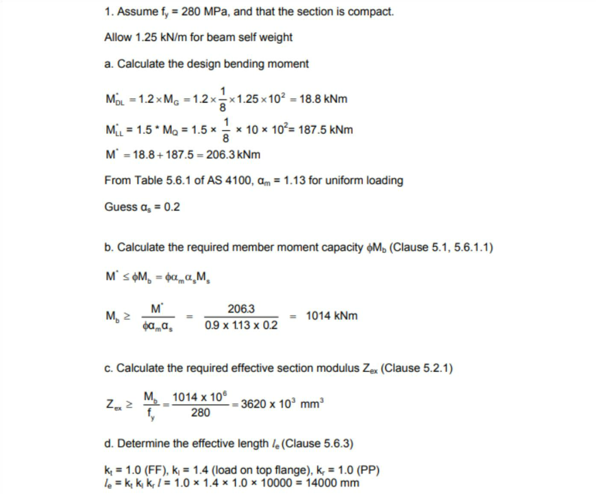
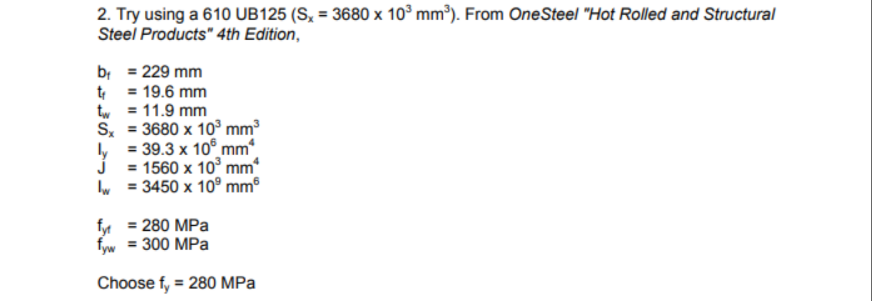
In the first part of the example, some assumptions and preliminary calculations are made to choose a potential beam to fit the design requirements.
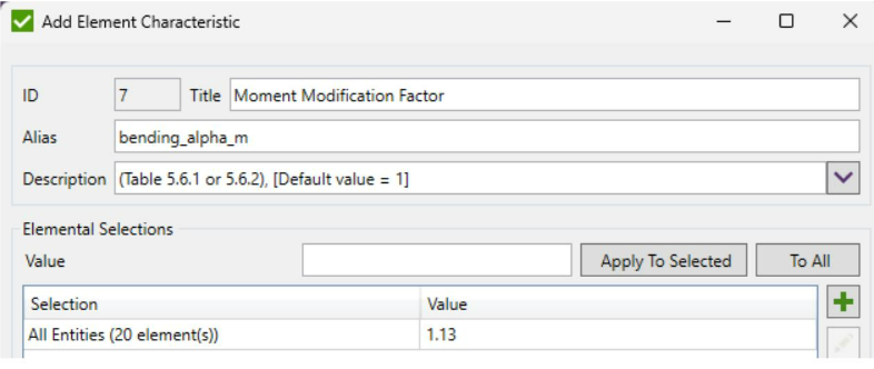
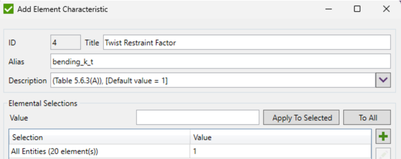
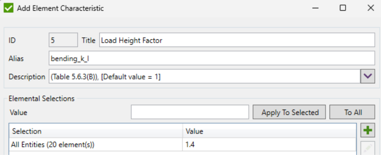
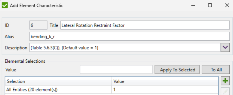
Based on the above the following Characteristics were defined:
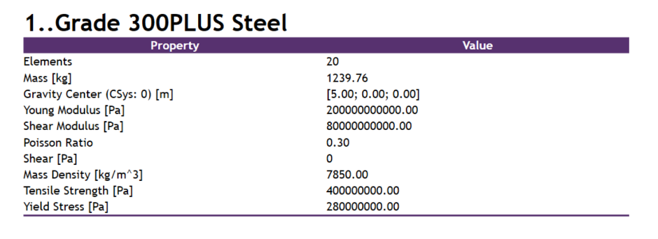
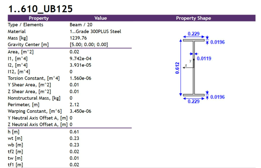
Based on the input parameters presented above a beam model was created with the following material and property definitions:
Note: Because of the limitations of the FEA software the cross-section is defined without fillets, so slight differences in geometrical properties are to be expected.
Where possible these values have been modified manually (as for the moments of inertia I1 and I2, torsion constant and warping constant in the table above), but some are calculated internally without the possibility to modify them (e.g. plastic section modulus).
Additionally, the yield stress is defined with one value for the beam property, so it’s the same for both the web and the flange, while in the problem definition, there is one value for the flange – 280 MPa, and a different value for the web – 300 MPa, so the lesser value was chosen.
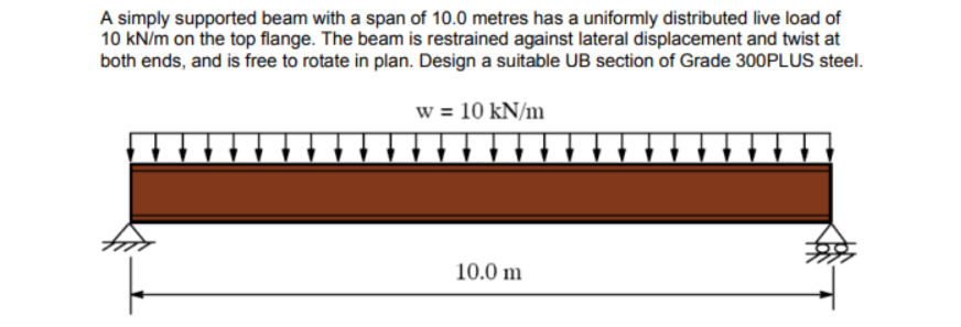
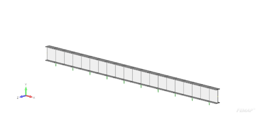
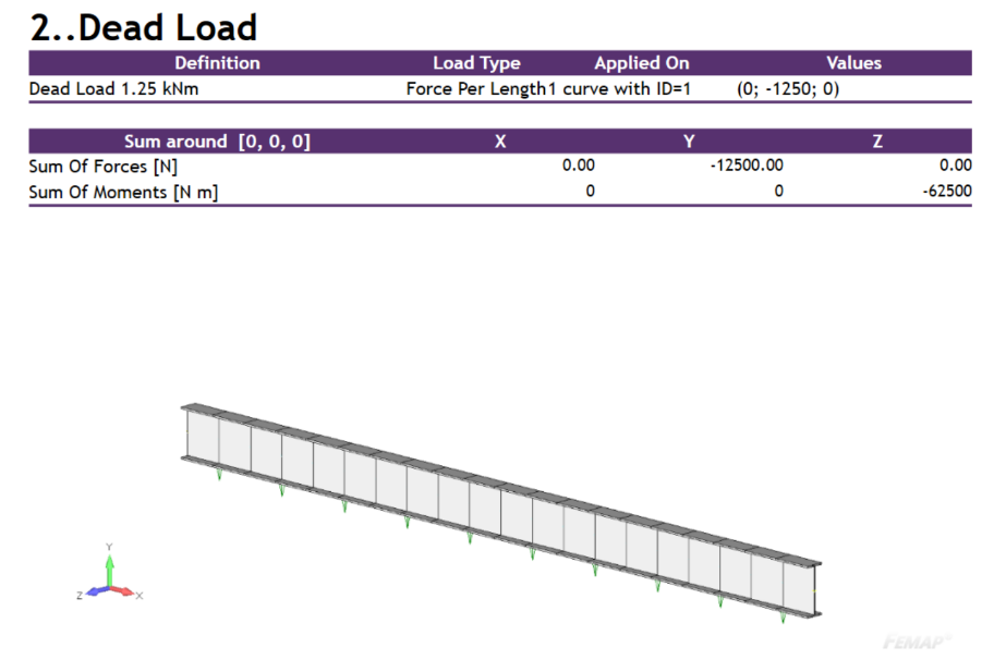
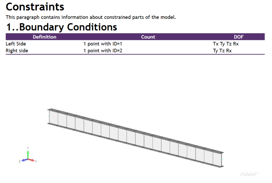
Loads and constraints have been defined according to the problem definition:
The loads are multiplied by the according factors using the SDC Verifier Load Set creator:
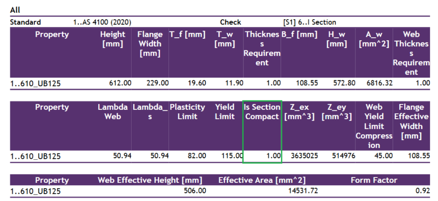
The above parameters are checked within a Property Check, in this case, one defined for I-Beam cross-sections.
SDC Verifier follows the logic presented in the standard, where out of the two checked slenderness values (for the flange and the web) the governing one is picked as the section slenderness (Lambda_s in the above table).
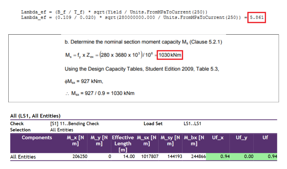
Although the example calculates only the value for the flange slenderness, we can see that following the logic in the standard the web slenderness is the governing value. Nevertheless, the flange slenderness can be checked in the calculation details, as presented below.
The value of the effective section modulus (Z_e) is lower than in the example (3635 ∗ 103 mm3 compared to 3680∗103 mm3, so by about 1.2%), because of the mentioned limitations of the FEA software.
We can also see the flag Is Section Compact which confirms that the section is in fact compact (1.00=yes).
As we can see the obtained value is slightly lower than in the example, but that’s due to the already mentioned lack of possibility to define fillets for the cross-section in the FEA software.
If we were to increase it by the 1.2% that was lost due to this inaccuracy in the plastic section modulus, we would obtain values that completely match (1017807 Nm∗101.2 %=1030 kNm).
Additionally, we can see that the effective length also matches the value obtained in the preliminary calculations:
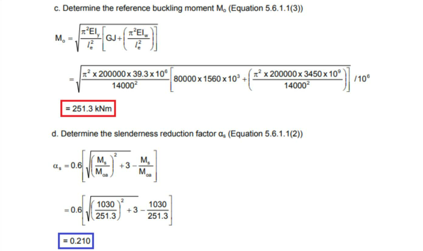
The reference buckling moment Mo and the slenderness reduction factor as are both calculated internally (not displayed in tables), but can be checked in the calculation details:
As we can see the reference buckling moment value matches completely and the slenderness reduction factor value is slightly above the one in the example due to using the underestimated nominal moment section capacity value in its calculation.
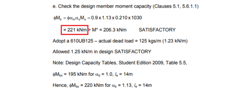
When calculating the nominal member moment capacity (M_bx) SDC Verifier follows the logic of the standard as well, so the multiplication by the capacity factor ? happens later when comparing it to the design bending moment.
That’s why the value obtained in the table has to be additionally reduced by ф for the purposes of the calculations in this example:
ф∗Mbx=0.9∗244866 Nm=220,4 kNm
As we can see the obtained value is slightly lower than in the example, but that’s due to the already mentioned lack of possibility to define fillets for the cross-section in the FEA software.
If the plastic section modulus could be modified to precisely represent the value in the example the obtained nominal member moment capacity value would match completely.
Whether the chosen section is satisfactory is confirmed in the SDC Verifier by obtaining a utilization factor (Uf) with a value below 1, which is additionally indicated by the green highlight in the table above
Gain Confidence in Your AS 4100 Beam Sizing Calculations
This benchmark demonstrated the use of SDC Verifier to streamline the beam sizing process for laterally unrestrained applications. Even with minor variances due to FEA software limitations, understanding these nuances ensures reliable results and AS 4100 code compliance.
This post uses screenshots from the Steel Structures Sample Worked Problems to AS 4100 document
