AS 4100. Example 7: Determine the Design Moment Capacity for the Major Axis for a Section also subject to Axial Compression
This benchmark was prepared based on
Australian Steel Institute (ASI) Steel Structures – Sample Worked Problems to AS 4100
using
SDC for Femap and Simcenter Femap Version 2022.2
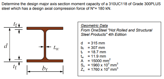
This benchmark focuses on determining the Design Moment Capacity (major axis) for a member under both axial compression and bending loads. You’ll learn about input parameters, FEA limitations, and how SDC Verifier 2024 R1 aligns with AS 4100 standards.
|
|
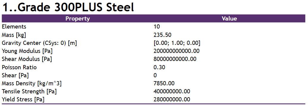
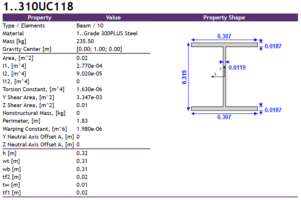
Based on the input parameters presented above a beam model was created with the following material and property definitions:
Note: Because of the limitations of the FEA software the cross-section is defined without fillets, so slight differences in geometrical properties are to be expected.
Where possible these values have been modified manually (as for the moments of inertia I1 and I1, torsion constant and warping constant in the table above), but some are calculated internally without the possibility to modify them (e.g. plastic section modulus).
Additionally, the yield stress is defined with one value for the beam property, so it’s the same for both the web and the flange, while in the problem definition there is one value for the flange – 280 MPa, and a different value for the web – 300 MPa, so the lesser value was chosen.
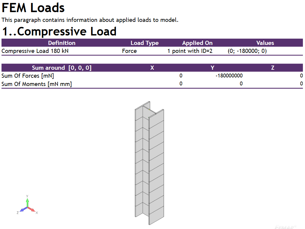
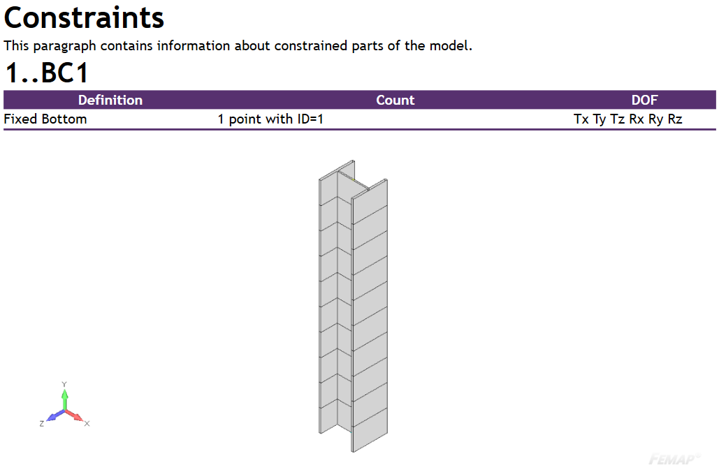
Loads and constraints have been defined according to the problem definition:
|
|
The above parameters are checked within a Property Check, in this case one defined for I-Beam cross-sections.
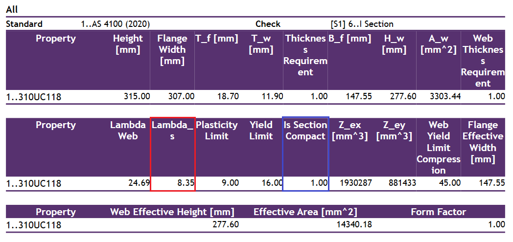
SDC Verifier follows the logic presented in the standard, where out of the two checked slenderness values (for the flange and for the web) the governing one is picked as the section slenderness (Lambda_s in the above table).
The value of the effective section modulus (Z_e) is lower than in the example (1960*103 mm3 compared to 1930*103 mm3, so by about 1.5%), because of the mentioned limitations of the FEA software. We can also see the flag Is Section Compact which confirms that the section is in fact compact (1.00=yes).
|
|
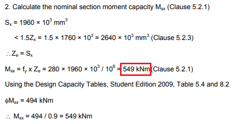
As we can see the obtained value is slightly lower than in the example, but that’s due to the already mentioned lack of possibility to define fillets for the cross-section in the FEA software. If we were to increase it by the 1.5% that was lost due to this inaccuracy in the plastic section modulus, we would obtain values that completely match (540481 Nm∗101.5 %=549 kNm).
|
|
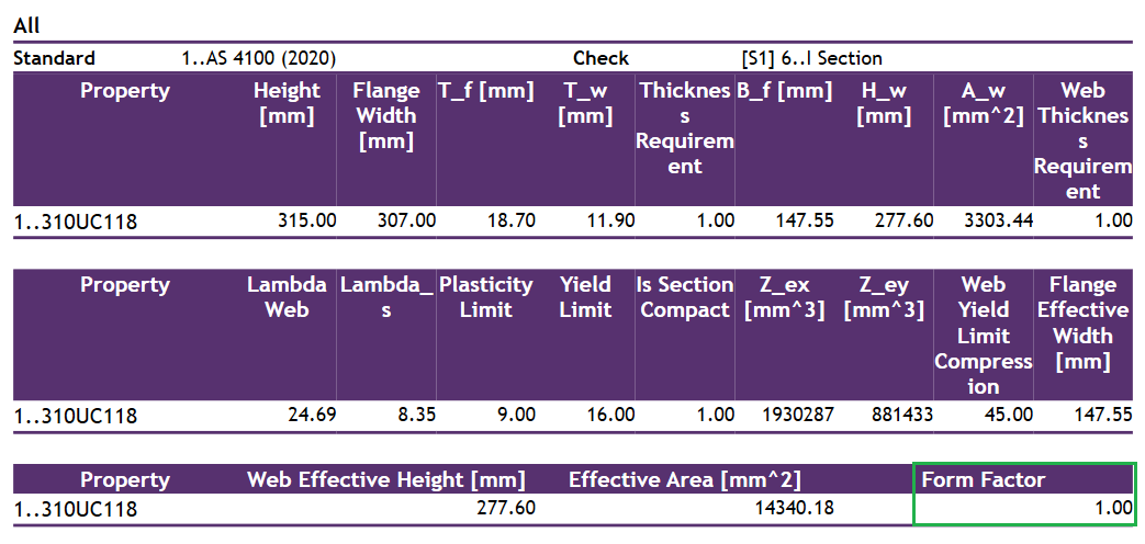
The slenderness form factor values are checked within a Property Check, in this case one defined for I-Beam cross-sections.
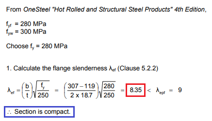
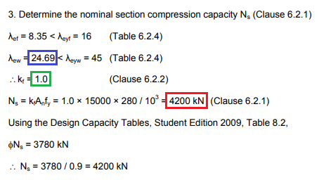
The flange slenderness was already calculated at an earlier stage and its value matches completely, it’s also assigned as the section slenderness, so it’s the value displayed in the table above. The web slenderness can additionally be checked in the calculation details, as presented below. The form factor value matches completely.
As we can see the nominal section compression capacity also matches the value in the example.
|
|
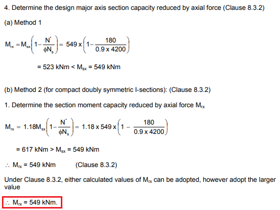
SDC Verifier by default uses Method 2 for all the possible cases (in this example for a compact doubly symmetric I-section).
As we can see the obtained value is slightly lower than in the example, but that’s due to the already mentioned lack of possibility to define fillets for the cross-section in the FEA software. If we were to increase it by the 1.5% that was lost due to this inaccuracy in the plastic section modulus, we would obtain values that completely match (540481 Nm∗101.5 %=549 kNm).
|
|
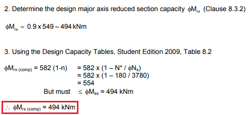
When calculating the reduced section moment capacity (M_rx) SDC Verifier follows the logic of the standard as well, so the multiplication by the capacity factor ф happens later when comparing it to the design bending moment. That’s why the value obtained above has to be additionally reduced by ф for the purposes of the calculations in this example:
ф∗Mrx=0.9∗549 kNm=494 kNm
As we can see the values completely match.
Gain Confidence in Combined Loading Calculations with SDC Verifier
While potential FEA software limitations may cause minor discrepancies, this benchmark demonstrates how SDC Verifier adheres to the logic of AS 4100 in calculating Design Moment Capacity for complex scenarios. Understanding these nuances aids in achieving reliable designs.
This post uses screenshots from the Steel Structures Sample Worked Problems to AS 4100 document
