Benchmarking SDC Verifier Against ASME BTH-1-2023: IPE600 Spreader Beam Compliance and Utilization
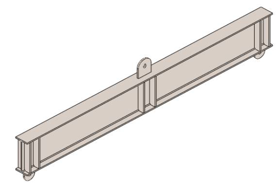
This benchmark analysis compares the accuracy of SDC Verifier (2024 R2) software with ASME BTH-1-2023 standard requirements for a spreader beam constructed using an IPE600 section.
The beam, designed for a 25-ton rated load under Design Category B, is assessed for compliance with key structural criteria such as bending stress, flange slenderness, and lateral bracing.
Both manual calculations and software verification are conducted to ensure that the SDC Verifier delivers reliable and accurate results that are in accordance with the standard.
In this example we will check whether a spreader beam composed of an IPE600 section passes the requirements from the BTH-1-2023 standard.
Design Parameters and Material Specifications
|
Design conditions |
|
| Code | ASME BTH-1-2023 |
| Rated Load | 25 t |
| Design Category | B |
| Nominal Design Factor | 3.00 |
| Load Cycles | 0 – 20 000 |
| Service Class | 0 |
| Fatigue Design Basis | No |
| General | |
| IPE600 | Section type |
| 25 t | m – Weight of the load |
| 3 | Nd – Design factor |
| Material | |
| S275JR | Material |
| 275 MPa | Fy – Yield strength |
| 200 GPa | E – Modulus of elasticity |
| Dimensions | |
| 4.5 m | L – Length of beam |
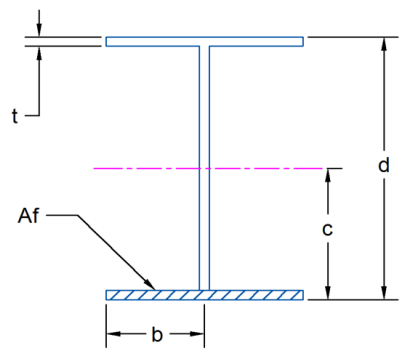
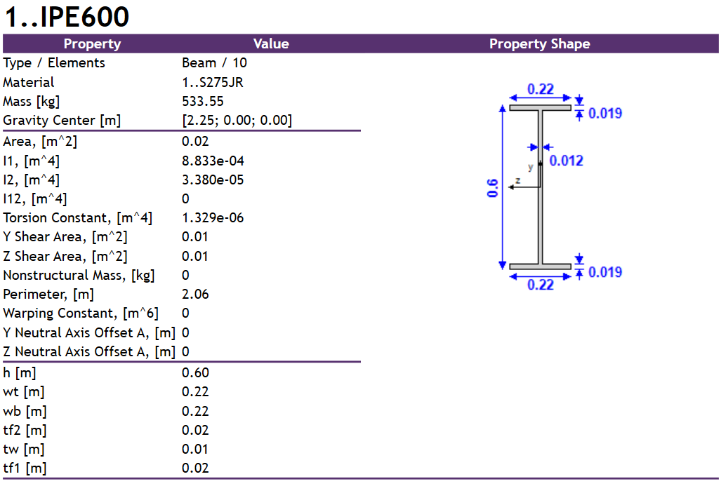
| 8.833 * 10-4 m4 | Ix – Major axis moment of inertia |
| 0.3 m | c – Distance to neutral axis |
| 0.6 m | d – Depth of section |
| 0.11 m | b – Half flange width |
| 0.019 m | tf – Flange thickness |
| 4.18 * 10-3 m2 | Af – Area of compression flange |
| 0.04731 m | ry – Minor axis radius of gyration |
Compactness and Flange Slenderness Verification
First, we check whether the section is compact as per Table 3-2.2-1.
Flange slenderness:
Limit from Table 3-2.2.1:
Flange type is compact:
Lateral Bracing and Bending Stress Calculations
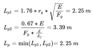
Now we check the lateral bracing interval as per eq. (3-7):
So, to use eq. (3-6) the gusset spacing can’t exceed 2.25 m for the allowable bending stress. With this assumption, we can calculate the allowable bending stress as per eq. (3-6):
Load resulting from the lifted weight:
Bending moment:
Computed bending stress:
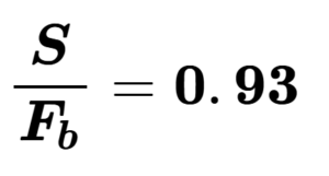
Utilization factor:
As we can see, a spreader beam composed of an IPE600 section in this configuration satisfies the requirements from BTH-1-2023 with an estimated utilization of 93% when lifting a 25 t load.
SDC Verifier Model Setup and Analysis
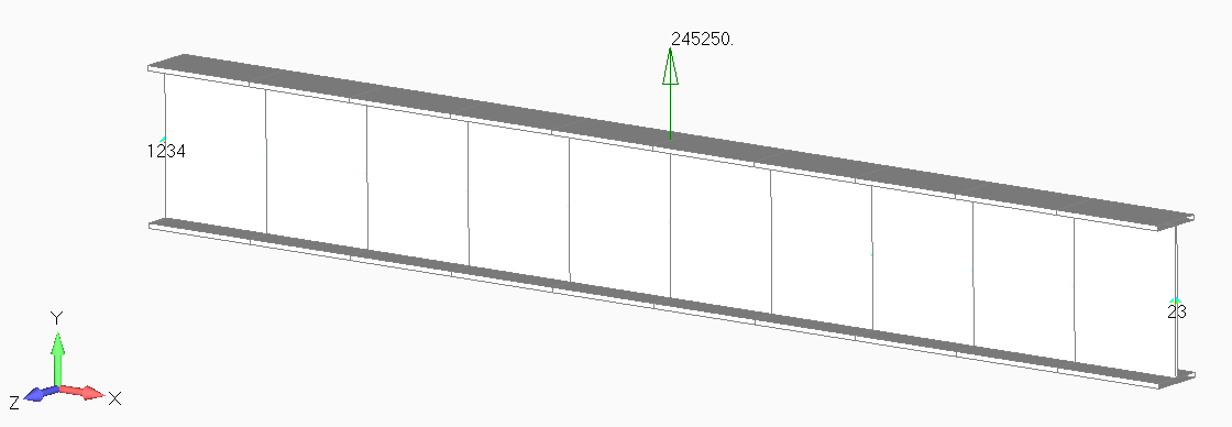
Now, we can recreate the above calculations in SDC Verifier (2024 R2) in combination with Simcenter Femap 2401. For that purpose, we built a simplified 1D beam model without the lugs and gussets.
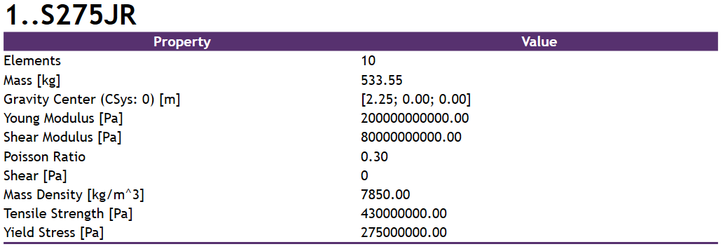
We can confirm the appropriate material and property definitions by generating the respective tables in Report Designer.
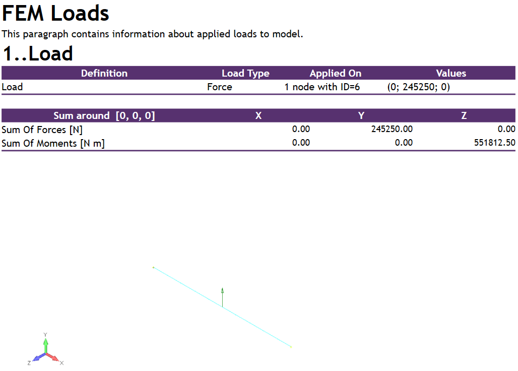
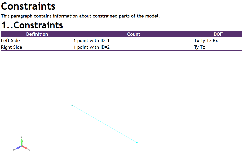
Similarly, the respective information can be given for loads and constraints.
With all the FEA inputs defined, we can define the standard inputs, specifically the nominal design factor Nd , which should be 3.00 for a Design Category B lifter.
Comparison of Hand Calculations and SDC Verifier Results
After this, we can start checking the results. The slenderness values and section compactness can be checked in the respective geometry check, in this case 4..I-Shape Section:
As we can see, the flange slenderness equals to 𝜆f=5.79, and the flange is compact (4.00 = compact, 5.00 = noncompact, 6.00 = slender).
The lateral bracing interval, as well as the allowable bending stresses, can be checked in check 11..Bending I-Shape Section:
The maximum gusset spacing resulting from the 𝑳𝒑 limit is 𝟐.𝟐𝟓𝒎 and the allowable bending stress in the major axis is 𝑭𝒃=𝟏𝟎𝟎.𝟖𝟑 𝑴𝑷𝒂.
Note: As we can see, the value of Lb equals 2.24m which is right below the Lp limit. By default, this value would equal the full member length as the beam was modeled in a simplified 1D approach, so 4.5m, but because we want to force the software to calculate the allowable bending strength according to eq. (3-6), we need to modify it manually. This can be done by first understanding how the Lb parameter is read from the model, which can be checked within the respective check formulae:
As we can see, this dimension is calculated by multiplying the K factor with the L length in the torsional direction from the Beam Member Finder recognition tool, so in order to have it be equal to our desired value, we can manually modify it there:
Finally, the computed bending stress and utilization factor can be checked in the 13..Bending Check:
The highest value of the computed bending stress in the major axis is 𝟗𝟑.𝟕𝟏 𝑴𝑷𝒂 and the resulting utilization factor is 0,93, which again confirms that a spreader beam composed of an IPE600 section in this configuration satisfies the requirements from BTH-1-2023.
Conclusion
This benchmark demonstrates that the SDC Verifier provides valid and accurate results compared to ASME BTH-1-2023 standards. With a utilization factor of 93%, the manual and software calculations confirm that the IPE600 section complies with the standard’s requirements.
| Flange slenderness | Lateral bracing interval | Allowable bending stress | Utilization factor | |
| Hand calculation |
5.79<10.25 compact |
5.25m | 100.83 MPa | 0.93 |
| SDC Verifier | 5.79<10.25 compact | 5.25m | 100.83 MPa | 0.93 |
The compactness of the flange section, bracing intervals, and allowable bending stresses are accurately validated, ensuring the structural reliability of the spreader beam design.
