Eurocode 3. Example 6.7: Buckling resistance of a compression member

We compare the buckling resistance of a compression member according to SDC Verifier and Designer’s Guide to Eurocode3: Design of steel buildings EN 1993-1-1.
The results are generated with SDC Verifier 4.5 and calculated with FEMAP v11.3.1
Task: A circular hollow section (CHS) member is to be used as an internal column in a multi-storey building. The column has pinned boundary conditions at each end, and the inter-storey height is 4m. The critical combination of actions results in a design axial force of 1630 kN. Assess the suitability of a hot-rolled 244.5 x 10 CHS in grade S355 steel for this application.

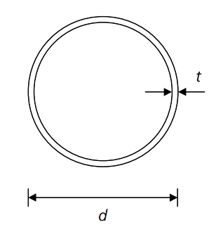
Figure 6.21. Section properties for 244.5×10 CHS
 |
|
Solution:
Model
Materials
| Title | Young Modulus [Pa] | Shear Modulus [Pa] | Poisson Ratio | Shear [Pa] | Mass Density [kg/m^3] | Tensile Strength [Pa] | Yield Stress [Pa] |
|---|---|---|---|---|---|---|---|
| 1..S355 | 2.10e+11 | 0 | 0.30 | 0 | 7850.00 | 470.00e+6 | 355.00e+6 |
Property “1..CHS 244.5 x 10”
| Property | Value | Property Shape |
|---|---|---|
| Type / Elements | Beam / 17 |  |
| Material | 1..S355 | |
| Mass [kg] | 231.3 | |
| Gravity Center [m] | [0.00; 0.00; 2.00] | |
| Area, [m2] | 0.0074 | |
| I1, [m4] | 5.073e-05 | |
| I2, [m4] | 5.073e-05 | |
| I12, [m4] | 0 | |
| Torsion Constant, [m4] | 1.014e-04 | |
| Y Shear Area, [m2] | 0.0039 | |
| Z Shear Area, [m2] | 0.0039 | |
| Nonstructural Mass, [kg] | 0 | |
| Perimeter, [m] | 0.77 | |
| Warping Constant, [m6] | 0 | |
| Y Neutral Axis Offset A, [m] | 0 | |
| Z Neutral Axis Offset A, [m] | 0 | |
| r [m] | 0.12225 | |
| t [m] | 0.01000 |
Boundary Conditions
Load “1..Axial -Z = 1630kN”
| Definition | Load Type | Applied On | Values |
|---|---|---|---|
| Force on Node | Force | Nodes: 18 | (0; 0; -1630000) |
 |
|||
Constraint “1..fixed”
| Definition | Count | DOF |
|---|---|---|
| Constraint on Node | Nodes: 1 | Tx Ty Tz |
| Constraint on Node | Nodes: 18 | Tx Ty Rz |
 |
Cross-section classification
| Check | 2..Circular Tube |
| Property | Shear Area | Diameter | Thickness | Epsilon | Lambda | Class | Buckling Curve | Imperfection Factor |
|---|---|---|---|---|---|---|---|---|
| 1..Tube | 0.0047 | 0.24450 | 0.01000 | 0.81 | 24.45 | 1.00 | 2.00 | 0.21 |
Cross-section classification (clause 5.5.2)
\[\varepsilon \ = \sqrt{235/f_{y}} \ = \sqrt{235/355} \ = 0.81\]
Tubular sections (Table 5.2, sheet 3):
\[d/t \ = 244.5/10.0 \ = 0.81\]
Limit for Class 1 section = 50ε2 = 40.7
40.7 > 24.5 ∴ section is Class 1
Cross-section compression resistance (clause 6.2.4)
| Standard | 1..Eurocode 3 Member Checks | Check | 9..Axial Check |
| Individual Load | 1..Axial -Z = 1630kN.fixed | Selection | 1..Eurocode3 Shapes |
| Extreme | Axial Force | Design Tension Resistance | Design Compression Resistance | Design Resistance | Utilization Factor |
|---|---|---|---|---|---|
| Minimum | -1630.0e+3 | 2615.3e+3 | 2615.3e+3 | 2615.3e+3 | -0.62 |
| Maximum | -1630.0e+3 | 2615.3e+3 | 2615.3e+3 | 2615.3e+3 | -0.62 |
| Absolute | -1630.0e+3 | 2615.3e+3 | 2615.3e+3 | 2615.3e+3 | -0.62 |
Cross-section compression resistance (clause 6.2.4)
\[N_{c,Rd} \ = \frac{Af_{y}}{\gamma M0} \]for Class 1, 2 or 3 cross-sections
\[∴ N_{c,Rd} \ = \frac{7370 \times 355 }{1.00} \ = 2616 \times 10^{3} N \ = 2616 kN\]2616 > 1630 kN ∴ cross-section resistance is acceptable
Member buckling resistance in compression (clause 6.3.1)
| Standard | 1..Eurocode 3 Member Checks | Check | 12..Buckling Axial |
| Individual Load | 1..Axial -Z = 1630kN.fixed | Selection | 1..Eurocode3 Shapes |
| Extreme | Ncr_y | Ncr_z | Lambda Y | Lambda Z | Fy | Fz | Xi_Y | Xi_Z | ||||
|---|---|---|---|---|---|---|---|---|---|---|---|---|
| Minimum | 6571.7e+3 | 6571.7e+3 | 0.63 | 0.63 | 0.74 | 0.74 | 0.88 | 0.88 | ||||
| Maximum | 6571.7e+3 | 6571.7e+3 | 0.63 | 0.63 | 0.74 | 0.74 | 0.88 | 0.88 | ||||
| Absolute | 6571.7e+3 | 6571.7e+3 | 0.63 | 0.63 | 0.74 | 0.74 | 0.88 | 0.88 | ||||
| Extreme | Nb Rd Y | Nb Rd Z | Uf_Y | Uf_Z | Uf | |||||||
| Minimum | 2296.0e+3 | 2296.0e+3 | -0.71 | -0.71 | -0.71 | |||||||
| Maximum | 2296.0e+3 | 2296.0e+3 | -0.71 | -0.71 | -0.71 | |||||||
| Absolute | 2296.0e+3 | 2296.0e+3 | -0.71 | -0.71 | -0.71 | |||||||
Member buckling resistance in compression (clause 6.3.1)
\[N_{b,Rd} \ = \frac{\chi Af_{Y}}{\gamma M1}\]for Class 1, 2 and 3 cross-sections
\[\chi \ = \frac{1}{\Phi + \sqrt{\Phi^{2} – \lambda^{2}}}\]but \[\chi \leq 1.0\]
where
\[\Phi \ = 0.5[1+\alpha(\lambda-0.2)+\lambda^{2}]\]and
\[\lambda \ = \sqrt{\frac{Af_{y}}{N_{cr}}}\]for Class 1, 2 and 3 cross-sections
Elastic critical force and non-dimensional slenderness for flexural buckling
\[N_{cr} \ = \frac{\pi^{2}EI}{L^{2}_{cr}} \ = \frac{\pi^{2} \times 210000 \times 50730000}{4000^{2}} \ = \color{red}{6571 kN}\] \[∴\lambda \ = \sqrt{\frac{7370 \times 355}{6571 \times 10^{3}}} \ = \color{green}{0.63}\]Buckling curves
\[\Phi \ = 0.5[1+0.21 \times (0.63 – 0.2)+0.63^{2}] \ = \color{orange}{0.74}\] \[\chi \ = \frac{1}{0.74 + \sqrt{0.74^{2} – 0.63^{2}}} \ = \color{blue}{0.88}\] \[∴N_{b,Rd} \ = \frac{0.88 \times 7370 \times 355}{1.0} \ = 2297 \times 10^{3} N \ = \color{yellow}{2297 kN}\]Conclusion
The chosen cross-section, 244.5 × 10 CHS in grade S355 steel is acceptable.
Cross-section compression and member buckling resistances in the SDC Verifier completely much with values in the example 6.7.
Check other comparisons of Eurocode3 design examples standard and SDC Verifier.
