Example D.4 Rectangular HSS tension member
The results of tensile yielding and recommended slenderness limit calculation according to SDC Verifier and Design Examples of AISC (official version 14.1) are compared. The goal is to test SDC Verifier and reach valid results according to Specification for Structural Steel Buildings (ANSI/AISC 360-10 chapter D).
The results are generated with SDC Verifier 3.6 and calculated with FEMAP v11.0.0
Task:
Verify the tensile strength of an HSS6×4×?, ASTM A500 Grade B, with a length of 30 ft. The member is carrying a dead load of 35 kips and a live load of 105 kips in tension. The end connection is a fillet welded ½-in. thick single concentric gusset plate with a weld length of 16 in. Assume that the gusset plate and weld are satisfactory.

Solution
From AISC Manual Table 2-4, the material properties are as follows:
- ASTM A500 Grade B
- Fy = 46 ksi
- Fu = 58 ksi
From AISC Manual Table 1-11, the geometric properties are as follows:
- HSS6×4×?
- Ag = 6.18 in.2
- ry = 1.55 in.
- t = 0.349 in.
From Chapter 2 of ASCE/SEI 7, the required tensile strength is:
Tensile Yielding
Check tensile yielding limit state using AISC Manual Table 5-4.
Check Recommended Slenderness Limit
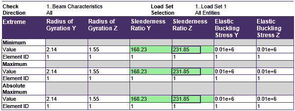
=232 < 300 from AISC Specification Section D1 o.k.
All units of measurement were chosen according to British metric system (lb, in, lb/in^3, lb/in^2).
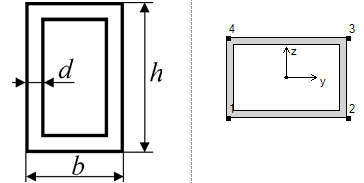
Material used is A500 Grade B with mass 631.84, Gravity Center 180.00; 0.00; 0.00 and property HSS6x4x?
| Geometry Property | Value |
|---|---|
| Height | 4.00 |
| Width | 6.00 |
| h | 4.00 |
| b | 6.00 |
| d | 0.35 |
Example from AISC Design Examples

From AISC Manual Table 1-11, the geometric properties are as follows:
- HSS6×4×?
- Ag = 6.18 in.2
- ry = 1.55 in.
- t = 0.349 in.
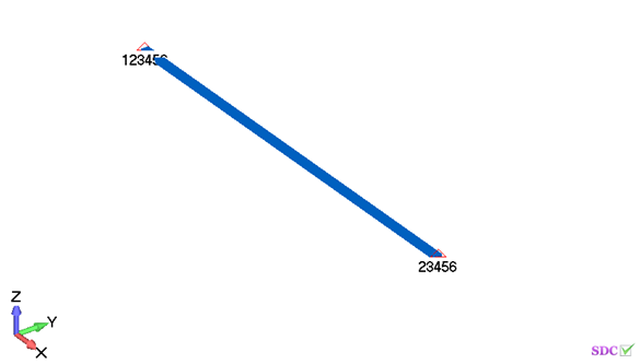
Note: HSS-beam was created in Femap (built-in section) with moment of inertia Iyy = 15.3 in^4 (fillets of rolled section weren’t taken into account), but in SDC Verifier moment of inertia was changed to Iyy = 14.4 in^4 according to the input data of the example.
FEM Loads and Constraint
2..Dead load 35 kips
| Definition Title | Load Type | Applied on | Value(s) |
|---|---|---|---|
| 1..Force on Node | Force | Node: 11 | (35000;0;0) |
3..Live load 105 kips
| Definition Title | Load Type | Applied on | Value(s) |
|---|---|---|---|
| 1..Force on Node | Force | Node: 11 | (105000;0;0) |
Constraint
| Definition | Count | Type (DOF) |
|---|---|---|
| 1..Fixed | 1 node(s) | Tx Ty Tz Rx Ry Rz |
| 2..Pinned | 1 node(s) | Ty Tz Rx Ry Rz |
Check 1..ANSI / AISC LRFD 360-10
Slenderness check
All (LS1, All Entities)
Check Recommended Slenderness Limit
Axial Check
All (LS1, All Entities)
From Chapter 2 of ASCE/SEI 7, the required tensile strength is:
Tensile Yielding
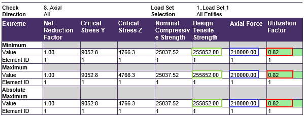
Check tensile yielding limit state using AISC Manual Table 5-4.
Comparing results of calculation in SDC Verifier and in Example D.4 we can see that values completely match.
- Tensile yielding stress is 256 kips > required tensile stress is 210 kips.
- Slenderness ratio Z is 232 < maximum slenderness limit for members in tension is 300 (AISC 360-10 chapter D.1).
Download SDC Verifier project file, model and report of Example D.4
