Example E.10 Rectangular HSS compression member with slender elements
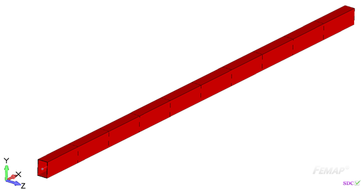
The results are generated with SDC Verifier 3.6 and calculated with FEMAP v11.0.0
Task:
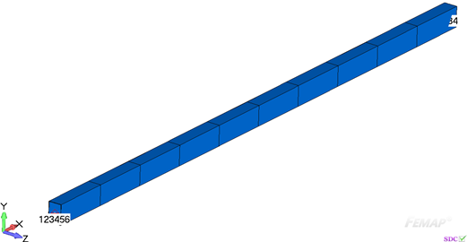
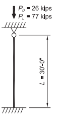
Select an ASTM A500 Grade B rectangular HSS12×8 compression member with a length of 30 ft, to support a dead load of 26 kips and live load of 77 kips. The base is fixed and the top is pinned.
A column with slender elements has been selected to demonstrate the design of such a member.
Solution:
From AISC Manual Table 2-4, the material properties are as follows:
- ASTM A500 Grade B
- Fy = 46 ksi
- Fu = 58 ksi
From Chapter 2 of ASCE/SEI 7, the required compressive strength is:
Table Solution
From AISC Specification Commentary Figure C-A-7.1, for a fixed-pinned condition, k = 0.8.
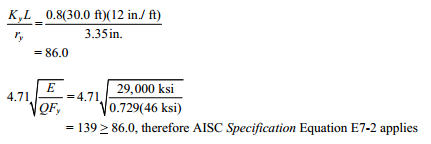
(KL)x = (KL)y = 0.8(30.0 ft) = 24.0 ft.
Enter AISC Manual Table 4-4 for HSS12×8 section and proceed to the lightest section with an available strength that is equal to or greater than the required strength, in this case an HSS12×8×3/16.
From AISC Manual Table 4-3, the available strength in axial compression is:
The available strength can be easily determined by using the tables of the AISC Manual. Available strength values can be verified by hand calculations, as follows, including adjustments for slender elements.
Calculation Solution
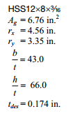
From AISC Manual Table 1-11, the geometric properties are as follows:
Slenderness Check
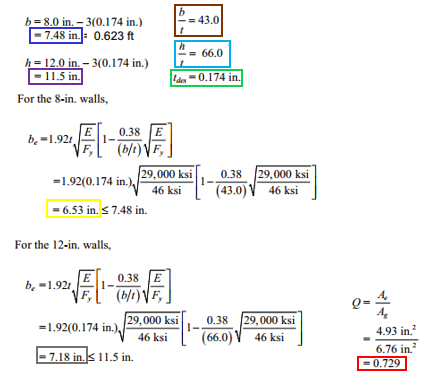
Calculate the limiting slenderness ratio, Λr, from AISC Specification Table B4.1a Case 6 for walls of HSS.
= 35.2 < 43.0 and <66.0, therefore both the 8-in. and 12-in. walls are slender elements.
Note that foe determining the width-to-thickness ratio, b is taken as the outside dimension minus three times the design wall thickness per AISC Specification Section B4.1b(d).
For the selected shape,
AISC Specification Section E7 is used for an HSS member with slender elements. The nominal compressive strength, Pn, is determined based upon the limit states of flexural buckling. Torsional buckling will not govern for HSS unless the torsional unbraced length greatly exceeds the controlling flexural unbraced length.
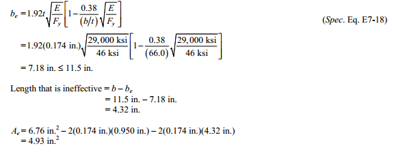
Effective Area, Ae
where Ae = summation of the effective areas of the cross section based on the reduced effective widths, be
For flanges of square and rectangular slender-element sections of uniform thikness,
where ƒ = Pn/Ae = summation of the effective areas of the cross section based on the reduced effective widths, be, but conservatively be taken as Fy according to the User Note in Specification Section E7.2.
For the 8-in. walls,
For the 12-in. walls,
For cross sections composed of only stiffened slender elements, Q = Qa(Qs = 1.0).
Critical Stress, Fcr
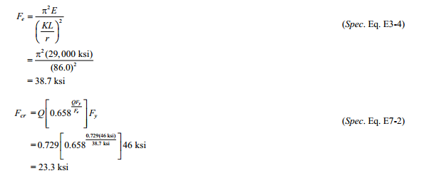
For the limit state of flexural buckling.
Nominal Compressive Strength
From AISC Specification Section E1, The available compressive strength is:
Note: A smaller available strength is calculated here because a conservative initial assumption (ƒ = Fy) was made in applying AISC Specification Equation E7-18. A more exact solution is obtained by iterating from the effective area, Ae, step using ƒ = Pn/Ae until the value of ƒ converges. The HSS column strength tables in the AISC Manual were calculated using this iterative procedure.
Example from AISC Design Examples
Material summary
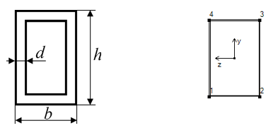
Properties Summary
| Geometry Property | Value |
|---|---|
| Height | 12.00 |
| Width | 8.00 |
| h | 12.00 |
| b | 8.00 |
| d | 0.174 |
FEM Loads and Constraint
1..Dead load 26 kips
2..Live load 77 kips
Constraint
1.. Pinned
Check 1..ANSI / AISC LRFD 360-10
Rectangular Tube
All (LS1, 3 PropertyShape(s))
For the selected shape,
Axial check
From Chapter 2 ASCE/SEI 7, the required compressive strength is:
From AISC Specification Section E1, the available compressive strength is:
Comparing results of calculation in SDC Verifier and in Example E.2 we can see that values completely match. The available compressive strength is 141.94 kips.
Download SDC Verifier project file, model and report of Example E.10
