Example E.11 Pipe compression member
The results are generated with SDC Verifier 3.6 and calculated with FEMAP v11.0.0
Task:
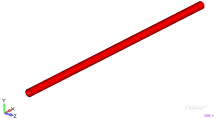
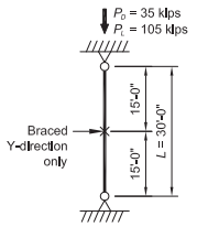
Select an ASTM A53 Grade B Pipe compression member with a length of 30 ft, to support a dead load of 35 kips and live load of 105 kips in axial compression. The column is pin-connected at the ends in both exes and braced at the midpoint in the y-y direction.
Solution:
From AISC Manual Table 2-4, the material properties are as follows:
- ASTM A53 Grade B
- Fy = 35 ksi
- Fu = 60 ksi
From Chapter 2 of ASCE/SEI 7, the required compressive strength is:
Table Solution
From AISC Specification Commentary Figure C-A-7.1, for a fixed-pinned condition, k =1.0.
Therefore, (KL)x = 30.0 ft and (KL)y = 15.0 ft. Buckling about the x-x axis controls.
Enter AISC Manual Table 4-6 with a KL of 30 ft and proceed across the table until reaching the lightest section with sufficient available strength to support the required strength.
Try a 10-in. Standard Pipe
From AISC Manual Table 4-6, the available strength in axial compression is:
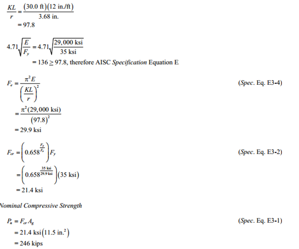
The available strength can be easily determined by using the tables of the AISC Manual. Available strength values can be verified by hand calculations, as follows.
Calculation Solution
From AISC Manual Table 1-14, the geometric properties are as follows:
Pipe 10 Std.
No pipes shown in AISC Manual Table 4-6 are slenderat 35 ksi, so no local buckling check is required; however, some round HSS are slender at higher steel strength. The following calculations illustrate the required check.
Limiting Width-to-Thickness Ratio
Λ <Λr therefore, the pipe is not slender
Critical Stress, Fcr
From AISC Specification Section E1, the available compressive strength is:
Note that the design procedure would be similar for a round HSS column
Example from AISC Design Examples
Material summary
Properties Summary
| Geometry Property | Value |
|---|---|
| Height | 10.80 |
| Width | 10.80 |
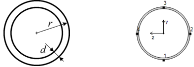
| r | 5.40 |
| d | 0.34 |
FEM Loads and Constraint
1..Dead load 35 kips
2..Live load 105 kips
Constraint
1.. Pinned
Check 1..ANSI / AISC LRFD 360-10
Beam Characteristics
All (LS1, All Entities)
Circular Tube
All (LS1, All Entities)
Axial check
All (LS1, All Entities)
From Chapter 2 ASCE/SEI 7, the required compressive strength is:
From AISC Specification Section E1, the available compressive strength is:
Note: Nominal Compressive Strength doesn’t match completely, because we can see difference of input data between two official documents: AISC 360-10 Examples and AISC Manual. From previous screenshot you can recognize difference with Ag =11.1 in2 in AISC Manual and with Ag =11.5 in2 in AISC 360-10 Examples.
Comparing results of calculation in SDC Verifier and in Example E.11 we can see that values completely match. The available compressive strength is 216.8 kips.
Download SDC Verifier project file, model and report of Example E.11
