


Example E.1A W-shape column design with pinned ends
The results are generated with SDC Verifier 3.6 and calculated with FEMAP v11.0.0
Task:
Select an ASTM A992 W-shape column to carry an axial dead load of 140 ksi and live load of 420 kips. The column is 30 ft long and is pinned top and bottom in both axes. Limit the column size to a nominal 14-in. shape.
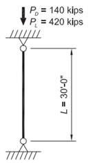
From Chapter 2 of ASCE/SEI 7, the required compressive strength is:
Column Selection
From AISC Specification Commentary Table C-A-7.1, for a pinned-pinned condition, K = 1.0.
Because the unbraced length is the same in both the x-x and y-y directions and rx exceeds ry for all W-shapes, y-y axis buckling will govern.
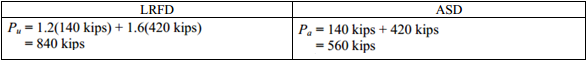
Enter the table with an effective length, KL, of 30 ft, and proceed across the table until reaching the least weight shape with an available strength that equals or exceeds the required strength. Select a W14×132.
From AISC Manual Table 4-1, the available strength for a y-y axis effective length of 30 ft is:

Material used is Steel ASTM A992 with mass 6844320.00, Gravity Center = 180.00; 0.00; 0.00 and property W14x132
Area, moment Izz, moment Iyy and other shape parameters are corrected because in FEMAP it calculated without fillets and chambers.
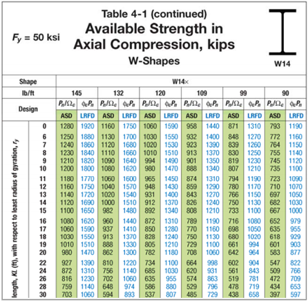
To check the corresponding properties for an idealized section, use the I-section moment of inertia and radius of gyration calculator. The benchmark itself uses corrected section properties to account for the rolled-profile geometry.
| Geometry Property | Value |
|---|---|
| Height | 14.70 |
| Width | 14.70 |
| h | 14.70 |
| a | 14.70 |
| b | 14.70 |
| c | 1.03 |
| d | 0.65 |
| t | 1.03 |
Example from AISC Design Examples
The properties are as follows:
- W14×132
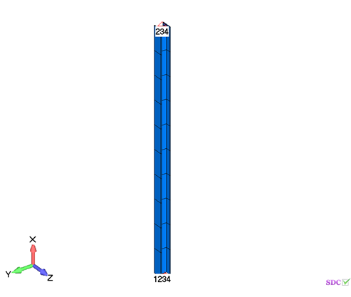
FEM Loads and Constraint
1..Dead load 140 kips
| Definition Title | Load Type | Applied on | Value(s) |
|---|---|---|---|
| 1.140 kips | Force | Node: 11 | (-140000;0;0) |
3..Live load 420 kips
| Definition Title | Load Type | Applied on | Value(s) |
|---|---|---|---|
| 1..420 kips | Force | Node: 11 | (-420000;0;0) |
Constraint
| Definition | Count | Type (DOF) |
|---|---|---|
| 1..Top | 1 node(s) | Ty Tz Rx |
| 2..Bottom | 1 node(s) | Tx Ty Tz Rx |
Check 1..ANSI / AISC LRFD 360-10
Axial check
All (LS1, All Entities)
From Chapter 2 of ASCE/SEI 7, the required compressive strength is:
![]()
From AISC Manual Table 4-1, the avaliable strength for a y-y axis effective length of 30 ft is:

Example E.1C W-shape column design with pinned ends
The results are generated with SDC Verifier 3.6 and calculated with FEMAP v11.0.0
Task:
Calculate the available strength of a W14×132 column with unbraced lengths of 30 ft in both axes. The material properties and loads are as given in Example E.1A.
Solution
From AISC Manual Table 2-4, the material properties are as follows:
ASTM A992
From AISC Manual Table 1-1, the geometric properties are as follows:
- W14×132
- Ag = 38.8 in.2
- rx = 6.28 in.
- ry = 3.76 in.
Slenderness Check
From AISC Specification Commentary Table C-A-7.1, for a pinned-pinned condition, K = 1.0.
Bacause the unbraced length is the same for both axes, the y-y axis will govern.
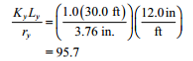
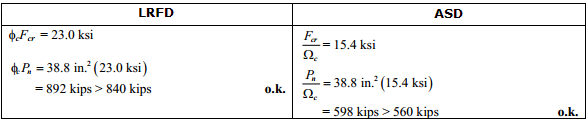
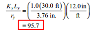
For Fy = 50 ksi, the available critical stresses, ΦcFcr/Ωc for KL/r = 95.7 are interpolated from AISC Manual Table 4-22 as follows:
Area, moment Izz, moment Iyy and other shape parameters are corrected because in FEMAP it calculated without fillets and chambers.
Beam Characteristics
All (LS1, 1 element(s))
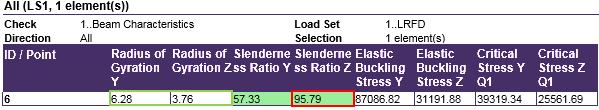
From AISC Manual Table 1-1, the geometric properties are as follows:

Bacause the unbraced length is the same for both axes, the y-y axis will govern
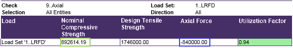
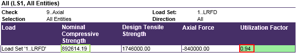
Axial check
All (LS1, All Entities)
For Fy = 50ksi, the available critical stresses, ΦcFcr and F>cr>/Ωc for KL/r = 95.7 are interpolated from AISC Manual Table 4-22 as follows:
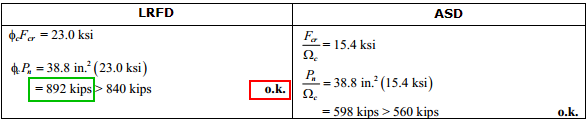
Comparing results of calculation in SDC Verifier and in Example E.1C and E. 1C we can see that values completely match.
The available strength for a y-y axis effective length of 30 ft is 893 kips.
Download SDC Verifier project file, model and report of Example E1A-1C


