


Example E.2 Built-up column with a slender web
The results are generated with SDC Verifier 3.6 and calculated with FEMAP v11.0.0
Task:
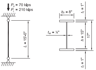
Verify that a built-up, ASTM A572 Grade 50 column with PL1 in. × 8 in. flanges and PL¼× 15 in. The web is sufficient to carry a dead load of 70 kips and live load of 210 kips in axial compression. The column length is 15 ft and the ends are pinned in both axes.
Solution:
From AISC Manual Table 2-5, the material properties are as follows:
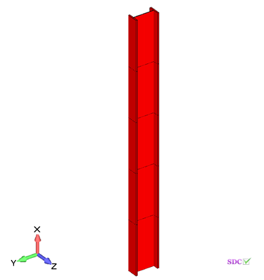
Built-up Column
- ASTM A572 Grade 50
- Fy = 50 ksi
- Fu = 65 ksi
The geometric properties are as follows:
Built-up Column
- d = 17.0 in.
- bf = 8.00 in.
- tf = 1.00 in.
- h = 15.0 in.
- tw = ¼in.
From Chapter 2 of ASCE/SEI 7, the required compressive strength is:

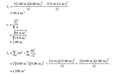
Built-up Section Properties (ignoring fillet welds)
A = 2(8.00 in.)(1.00 in.) + 15.0 in.(¼ in.)= 19.8 in2.
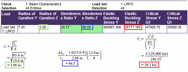
Elastic Flexural Buckling Stress
From AISC Specification Commentary Figure C-A-7.1, for a pinned-pinned condition, k = 1.0.
Because the unbraced length is the same for both axes, the y-y axis will govern by inspection.
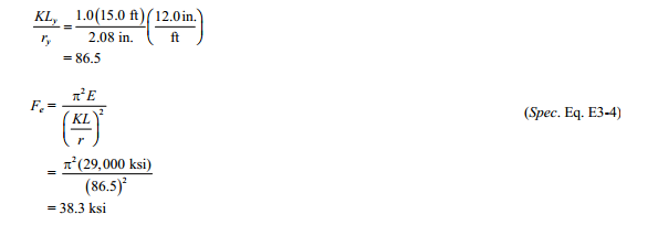
Elastic Flexural Buckling stress
Note: Torsional buckling generally will not govern if KLy ≥ KLz; however, the check is included here to illustrate the calculation.
From the User Note in AISC Specification Section E4,
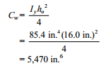
From AISC Design Guide 9, Equation 3.4,
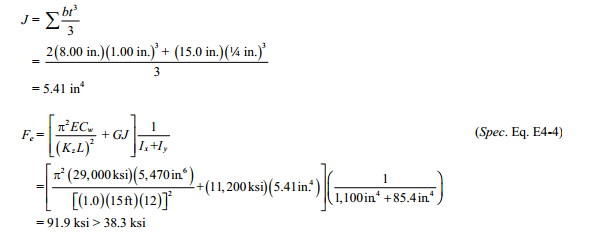
Therefore, the flexural buckling limit state controls.
Use Fe = 38.3 ksi.
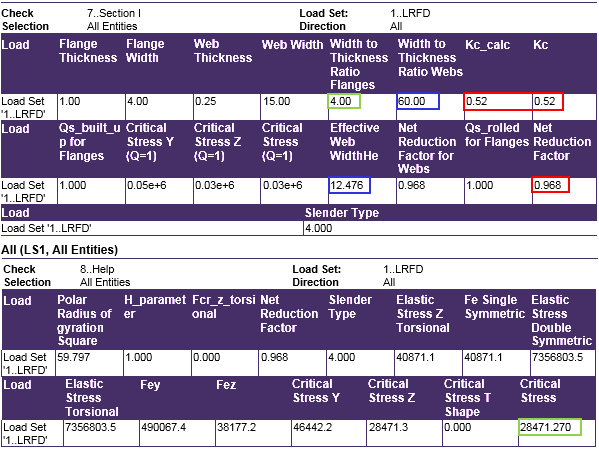
Slenderness
Check for slender flanges using AISC Specification Table B4.1a, then determine Qs, the unstiffened element (flange) reduction factor using AISC Specification Section E7.1.
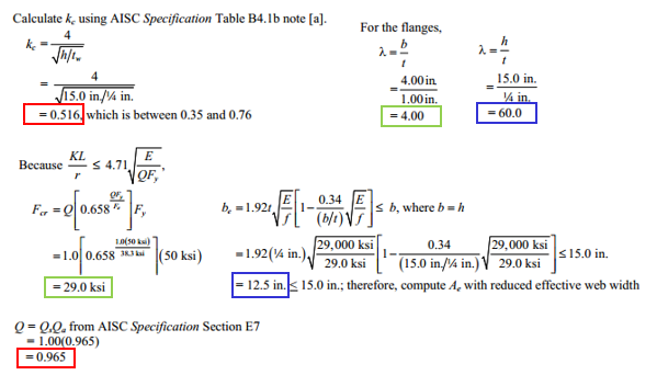
Calculate kc using AISC Specification Table B4.1b note [a]
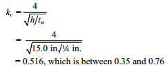
For the flanges,

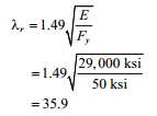
Determine the flange limiting slenderness ratio, Λr, from AISC Specification Table B4.1a Case 2.
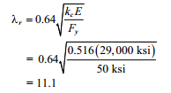
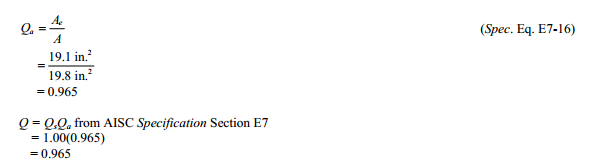
Λ < Λr therefore, the flange is not slender and Qa = 1.0.
Check for slender web, then determine Qs, the stiffened element (web) reduction factor using AISC Specification Section E7.2.
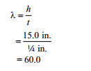
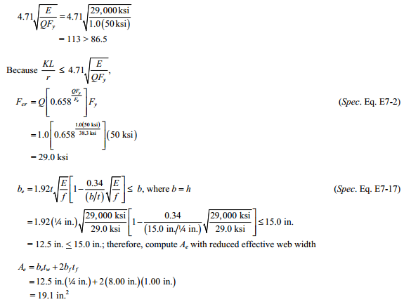
Determine the slender web limit from AISC Specification Table B4.1a Case 5.
Λ > Λr therefore, the web is slender
![]()
where Ae = effective area based on the reduced effective width, be
From AISC Specification Equation E7-17, take ƒ as Fcr with Fcr calculated based on Q = 1.0.
Equations E7-2 and E7-3 based on KL/ry.
KL/r = 86.5 as previously calculated
Flexural Buckling Stress
Determine whether AISC Specification Equation E7-2 or E7-3 applies.
KL/r = 86.5 as previously calculated
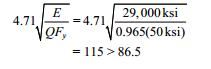
Therefore, AISC Specification Equation E7-2 applies.
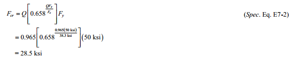
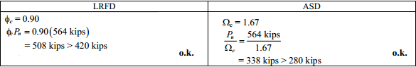
Nominal Compressive Strength

From AISC Specification Section E1, the available compressive strength is:
Example from AISC Design Examples
Material summary![]()
Properties Summary

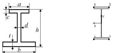
| Geometry Property | Value |
|---|---|
| Height | 17.00 |
| Width | 8.00 |
| h | 17.00 |
| a | 8.00 |
| b | 8.00 |
| c | 1.00 |
| d | 0.25 |
| t | 1.00 |
FEM Loads and Constraint
1..Dead load 70 kips
![]()
2..Live load 210 kips
![]()
Constraint
1.. Pinned
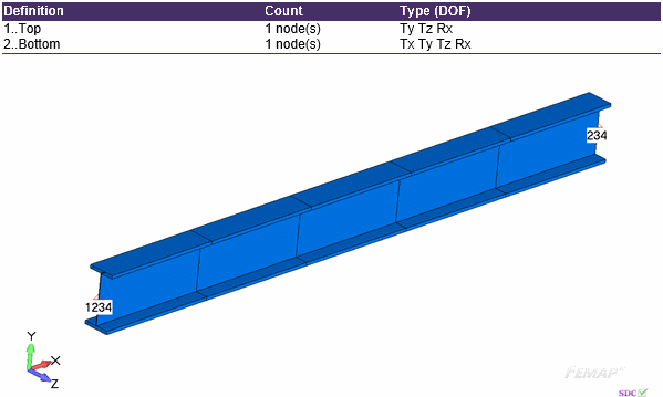
Check 1..ANSI / AISC LRFD 360-10
Beam Characteristics
All (LS1, All Entities)
Axial check
All (LS1, 1 element(s))
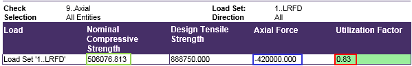
Nominal Compressive Strength

From AISC Specification Section E1, the available compressive strength is:
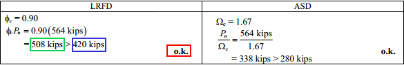
Comparing results of calculation in SDC Verifier and in Example E.2 we can see that values completely match. The available compressive strength is 506 kips. Example E2


