


Example E.7 WT compression member without slender elements
The results are generated with SDC Verifier 3.6 and calculated with FEMAP v11.0.0
Task:
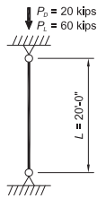
Select an ASTM A992 nonslender WT-shape compression member with a length of 20 ft to support a dead load of 60 kips and live load of 60 kips in axial compression. The ends are pinned.
Solution:
From AISC Manual Table 2-4, the material properties are as follows:
- ASTM A992
- Fy = 50 ksi
- Fu = 65 ksi
From Chapter 2 of ASCE/SEI 7, the required compressive strength is:

Table Solution
From AISC Specification Commentary Figure C-A-7.1, for a pinned-pinned condition, k = 1.0.
Therefore, (KL)x = (KL)y = 20.0 ft.
Select The lightest nonslender member from AISC Manual Table 4-7 with sufficient available strength about both the x-xaxis (upper portion of the table) and the y-y axis (lower portion of the table) to support the required strength.
Try a WT7×34.
The available strength in compression is:
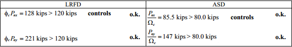
The available strength can be easily determined by using the tables of the AISC Manual. Available strength values can be verified by hand calculations, as follows
Calculation Solution
From AISC Manual Table 1-8, the geometric properties are as follows:
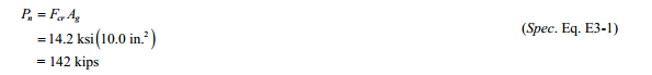
- WT7×34.
- Ag = 10.0 in2.
- rx = 1.81 in.
- ry = 2.46 in.
- J = 1.50 in4.
- γ‾ = 1.29 in.
- I x = 32.6 in4.
- I y = 60.7 in4.
- d = 7.02 in.
- tw = 0.415 in.
- bf = 10.0 in.
- tf = 0.720 in.
Stem Slenderness Check
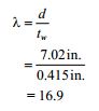
Determine the stem limiting slenderness ratio, Λr, from AISC Specification Table B4.1a Case 4.
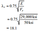
Λ < Λr therefore, the stem is not slender.
Flange Slenderness Check
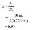
Determine thr flange limiting slenderness ratio, Λr, from AISC Specification Table B4.1a Case 1.
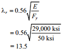
Λ < Λr therefore, the flange is not slender.
There are no slender elements.
For compression members without slender elements, AISC Specification Sections E3 and E4 apply. Then nominal compressive strength, Pn shall be determined based on the limit states of flexural, torsional and flexural-torsional buckling.
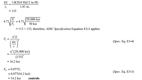
Flexural Bucking about the x-x axis
Torsional and Flexural-Torsional Buckling
Because the WT7×34 section does not have any slender elements, AISC Specification Section E4 will be applicable for torsional and flexural-torsional buckling. Fcr will be calculated using AISC Specification Equation E4-2.
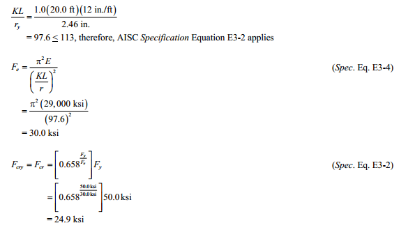
Calculate Fcry.
Fcry is taken as Fcr from AISC Specification Section E3, where KL/r = KL/ry.
The shear center for a T-shaped section is located on the axis of symmetry at the mid-depth of the flange.
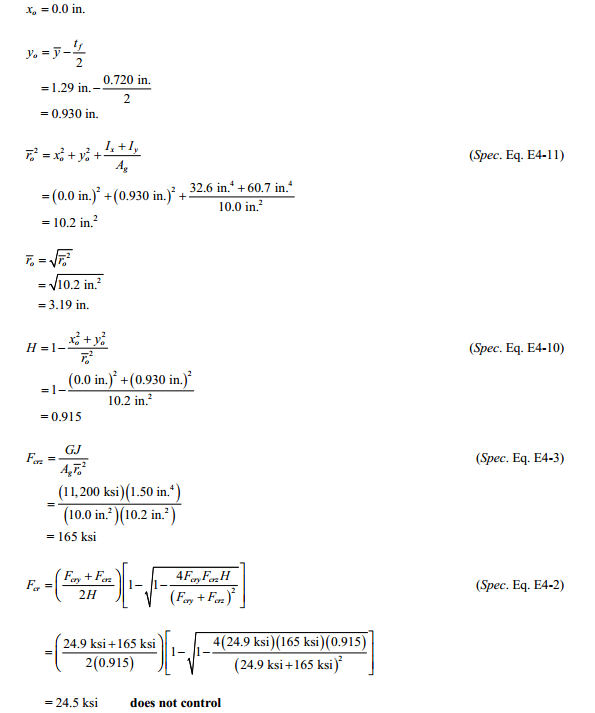
x-x axis flexural buckling governs, therefore,
From AISC Specification Section E1, the available compressive strength is:
Example from AISC Design Examples
Material summary
![]()
Properties Summary
1..WT7×34
![]()
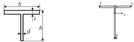
| Geometry Property | Value |
|---|---|
| Height | 7.02 |
| Width | 10.00 |
| h | 7.02 |
| b | 10.00 |
| d | 0.42 |
| t | 0.72 |
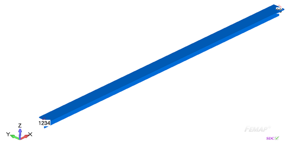
FEM Loads and Constraint
1..Dead load 20 kips
![]()
2..Live load 60 kips
![]()
Constraint
1.. Pinned

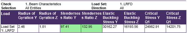
Check 1..ANSI / AISC LRFD 360-10
Beam Characteristics
All (LS1, All Entities)
Axial check
All (LS1, All Entities)
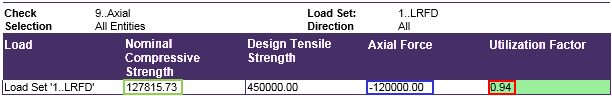
From AISC Specification Section E1, the available compressive strength is:
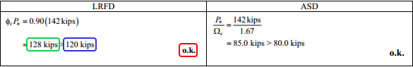
Comparing results of calculation in SDC Verifier and in Example E.7 we can see that values completely match. The available compressive strength is 128 kips.
Download SDC Verifier project file, model and report of Example E.7


