


Example F.5 I-shape flexural member in minor-axis bending
The results are generated with SDC Verifier 3.6 and calculated with FEMAP v11.0.0
Task:
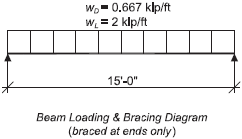
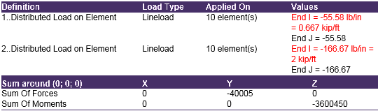
Select an ASTM A 992 W-shape flexural beam loaded in its minor axis with a simple span of 15 ft. The loads are a total uniform dead load of 0.667 kip/ft and a uniform live load of 2 kip/ft. Limit the live load deflection to L/240. The beam is braced at the ends only.
Note: Although not a common design case, this example is being used to illustrate AISC Specification Section F6 (I-shape members and channels bent about their minor axis).
Solution:
From AISC Manual Table 2-4, the material properties are as follows:
- ASTM A992
- Fy = 50 ksi
- Fu = 65 ksi
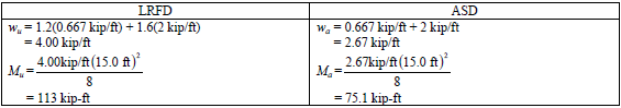
From Chapter 2 of ASCE/SEI 7, the required flexural strength is:
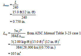
Minimum Required Moment of Inertia
The maximum live load deflection permitted is:
Beam Selection
Select the lightest section from the bold entries in AISC Manual Table 3-5, due to the likelihood that deflection will govern this design.
- Try s W12×58
From AISC Manual Table 1-1, the geometric properties are as follows:
- W12×58
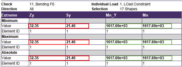
- Sy = 21.4 in3.
- Zy = 32.5 in3.
- Iy = 107 in4 >105 in 4. o.k.
AISC Specification Section F6 applies. Because the W12×58 has compact flanges per the User Note in this Section, the yielding limit state governs the design.
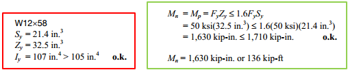
- Mn = Mp = FyZy ≤1.6FySy
- = 50 ksi 32.5 in3 )≤1.6(50 ksi)(21.4 in 3)
- =1.630 kip-in. ≤1.710 kip-in. o.k
- Mn = 1.630 kip-in. or 136 kip-ft
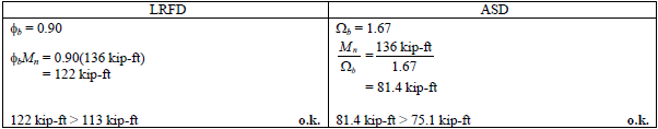
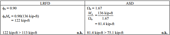
From AISC Specification Section F1, the available flexural strength is:
Units which was used in calculation:
- 1 kip = 1000lb
- 1 ft = 12 in
- 1 ksi = 1000 psi (lb/in^2)
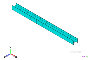
Example from AISC Design Examples
Material summary
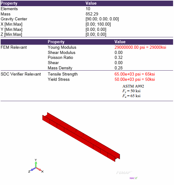
Properties Summary
![]()
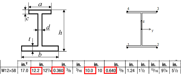
| Geometry Property | Value |
|---|---|
| Height | 12.20 |
| Width | 10.00 |
| h | 12.20 |
| a | 10.00 |
| b | 10.00 |
| c | 0.64 |
| d | 0.36 |
| t | 0.64 |
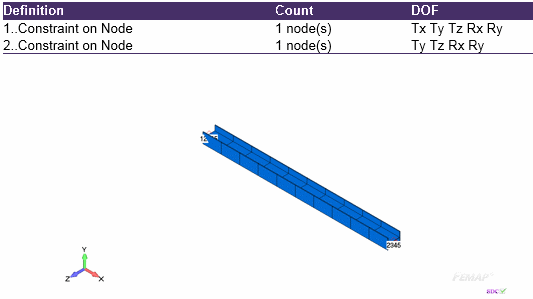
FEM Loads and Constraint
1..Load
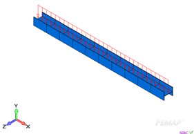
Constraint
Individual Load ‘1..Load.Constraint’
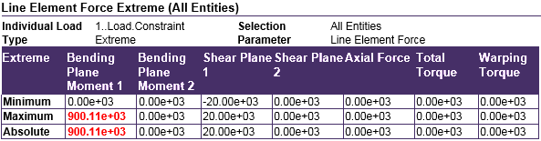
From Chapter 2 of ASCE/SEI 7, the required flexural strength is:
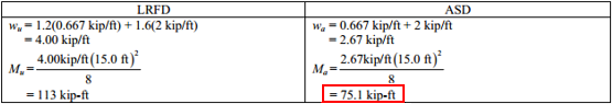
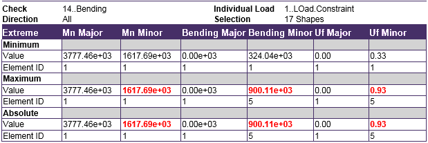
900.11e+03 lb-in = 75 kip-ft
Check 1..ANSI / AISC LRFD 360-10
1..Bending – chapter F6 (Design of Member for Flexure)
All (IL1, 17 Shapes)
2..Bending – final results
All (IL1, 17 Shapes)
From AISC Specification Section F1, the available flexural strength is:
Utilization factor
- 1617 kip-in = 134.75 kip-ft;
- 900 kip-in = 75 kip-ft;
- 81.4/75.1 = 0.93
Comparing results of calculation with SDC Verifier and Example F.5 can be seen that values coincide. Slight difference was explained by converting units from one to another.
The required flexural strength is 900 kip-in.


