Fatigue Life: Key Influencing Factors and Advanced Prediction Methods

Understanding fatigue life is crucial in structural engineering to ensure components’ long-term reliability and safety under cyclic stresses.
This post will explore the factors influencing fatigue life, prediction methods, and techniques in fatigue analysis. It will offer a comprehensive guide for engineers and professionals to design safer, longer-lasting structures.
Read our previous topics in our Fundamentals of Fatigue article series:
Understanding Fatigue Life
Before we delve into the complexities of fatigue life analysis, let’s take a moment to understand the fundamental concept of fatigue failure.
Fatigue life is the number of cycles a material or component can endure before failure occurs due to repeated loading and unloading. Various stress values are considered when calculating fatigue life, including the nominal maximum stress, typically smaller than the ultimate tensile stress limits. The yield stress limit is another value that could be greater than the final tensile stress limits.
Material design can increase stress on objects, with sharper angles like corners in squares causing higher stress areas than rounded areas, distributing the load evenly.
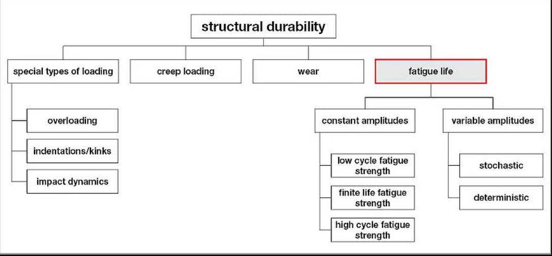
This diagram illustrates the various factors that contribute to structural durability, highlighting fatigue life as a key consideration alongside other loading types.
Image: zwickroell.com
By understanding fatigue life, you can design structures subjected to cyclic stresses, ensuring they can operate safely throughout their intended lifespan.
Importance of Fatigue Life in Structural Engineering and Design
- Ensures Longevity and Reliability of Structures. Engineers can design structures that remain safe and functional over extended periods by accurately predicting fatigue life. This helps in critical applications such as bridges, aircraft, and offshore platforms, where failure can have severe consequences.
- Helps Prevent Unexpected Failures. This allows for the implementation of maintenance schedules and inspection routines to identify and mitigate potential failures before they occur. This proactive approach reduces the risk of unexpected downtime and associated costs.
- Guides the Selection of Appropriate Materials and Design Parameters. Fatigue life data informs the choice of materials and design configurations that optimize durability and performance. Engineers can select materials with favorable fatigue properties and design components to minimize stress concentrations, enhancing overall structural integrity.
Incorporating fatigue life considerations into the engineering process results in more durable and reliable designs, ultimately enhancing safety, performance, and cost-effectiveness across various industries.
Also, Fatigue assessments of crane structures should be performed by standards like Eurocode 3, EN, FEM, DNV, and ABS.
Factors Influencing Fatigue Life in Structural Engineering
Several factors influence the fatigue life of materials and components in structural engineering. These factors include the material properties, load characteristics, environmental conditions, and manufacturing processes.
| Factor | Description | Impact on Fatigue Life |
| Stress Level | Magnitude and type of cyclic stress (e.g., tension, compression, bending) | Higher stress levels generally lead to shorter life. |
| Material | Type of material (e.g., steel, aluminum, composite), its microstructure, and surface finish | Different materials have varying fatigue strengths. |
| Load Type | Nature of loading (e.g., constant amplitude, variable amplitude, random) | Variable amplitude loading can be more damaging. |
| Environment | Temperature, humidity, corrosive agents | Harsh environments accelerate fatigue damage. |
| Manufacturing | Processes used to create the component (e.g., welding, casting, machining) | Can introduce residual stresses and affect fatigue. |
Stages of Fatigue Failure in Structure
Structural fatigue failure typically progresses through crack initiation, propagation, and final fracture. Each stage is characterized by specific phenomena and influences that ultimately lead to the failure of the structural component.
1. Crack Initiation
Crack initiation is the first stage of fatigue failure, where microscopic cracks form in the material. This stage is often the most prolonged and can be influenced by several factors:
- Stress Concentrators: Areas with stress concentrators, such as notches, holes, sharp corners, and surface scratches, are common sites for crack initiation. These imperfections create localized stress fields significantly higher than the nominal stress, leading to the nucleation of cracks.
- Surface Roughness: Rough surfaces, often resulting from manufacturing processes like machining or casting, can be initiation points for fatigue cracks. Smoother surfaces tend to have more extended fatigue lives as they reduce the likelihood of stress concentration.
- Residual Stresses: Residual stresses introduced during manufacturing or processing can influence crack initiation. Compressive residual stresses can be beneficial by impeding crack formation, while tensile residual stresses can accelerate crack initiation.
- Material Defects: Inherent defects in the material, such as inclusions, voids, or grain boundaries, can act as initiation sites. The presence of these defects can significantly reduce the fatigue life of the material.
2. Crack Propagation
Once a crack has initiated, it propagates through the material under cyclic loading. Several factors influence the crack propagation stage:
- Stress Intensity Factor (ΔK): The stress intensity factor range (ΔK) is a critical parameter that drives crack growth. It quantifies the stress state near the crack tip and influences the crack’s rate of growth. Higher ΔK values generally lead to crack propagation faster.
- Load Ratio (R): The load ratio (R), defined as the minimum load divided by the maximum load in a loading cycle, affects fatigue crack growth behavior. Positive load ratios (R > 0) typically result in slower crack growth compared to negative load ratios (R < 0).
- Crack Closure: Crack closure phenomena, where the fatigue crack faces come into contact during part of the loading cycle, can reduce the influential stress intensity factor and slow down crack growth. Material properties, load levels, and environmental conditions influence this effect.
- Environmental Effects: Environmental conditions, such as temperature, humidity, and corrosive media, can significantly impact fatigue crack growth rates. Corrosive environments, for example, can lead to accelerated crack propagation through mechanisms like stress corrosion cracking or corrosion fatigue.
3. Final Fracture
The final fracture stage occurs when the remaining cross-sectional area of the material can no longer support the applied load, leading to catastrophic failure. This stage is characterized by:
- Rapid Crack Growth: As the crack grows, the remaining material’s ability to bear the load diminishes, causing the crack to propagate rapidly until failure. An acceleration in the crack growth rate often marks this phase.
- Brittle or Ductile Fracture: The nature of the final fracture depends on the material properties and loading conditions. A brittle fracture occurs with minimal or no plastic deformation, typically characterized by a flat fracture surface with distinct features such as chevron marks or river patterns. Ductile fracture, conversely, involves significant plastic deformation characterized by a fibrous or dimpled fracture surface.
- Fracture Surface Features: The fracture surface in the final stage often reveals features indicative of the material’s failure mode. The surface may show cleavage facets or intergranular cracking in brittle fractures, while ductile fractures exhibit dimple patterns resulting from micro-void coalescence.
- Energy Absorption: The final fracture stage involves releasing stored elastic energy in the material. Ductile materials absorb more energy during fracture, resulting in more extensive plastic deformation and less sudden failure. Brittle materials, however, absorb less energy and fail more abruptly.
Prediction Methods for Fatigue Life in Structural Engineering
When it comes to designing durable structures, predicting fatigue life is critical. The following methods provide tailored insights based on the type of stress and strain a component will encounter:
Stress-Life (S-N) Method
The stress-life technique is employed when the applied stress is primarily within the elastic range, and the material has a long cycle life. It involves plotting the applied stress (S) against the number of cycles to failure (N) on a logarithmic scale, creating an S-N curve.
The stress-life approach is used in situations with a fatigue life exceeding 103 cycles, assuming only elastic strains are effective. This assumption introduces computational errors, as plastic strains from plastic deformation are recognized fatigue crack initiation protocols.
Such an approach is widely used in designing bridges and high-rise buildings where components are subjected to repeated but relatively low stress levels over a long period. For instance, engineers use S-N curves in bridge construction to ensure that materials can endure the repetitive loads from traffic and environmental factors over decades without failing.
Strain-Life Method
The strain-life approach is especially beneficial at high-stress levels or in areas with high-stress concentrations and significant plastic strain. Such stress has a short propagation life. Thus, the strain-life technique solely considers the fracture initiation period.
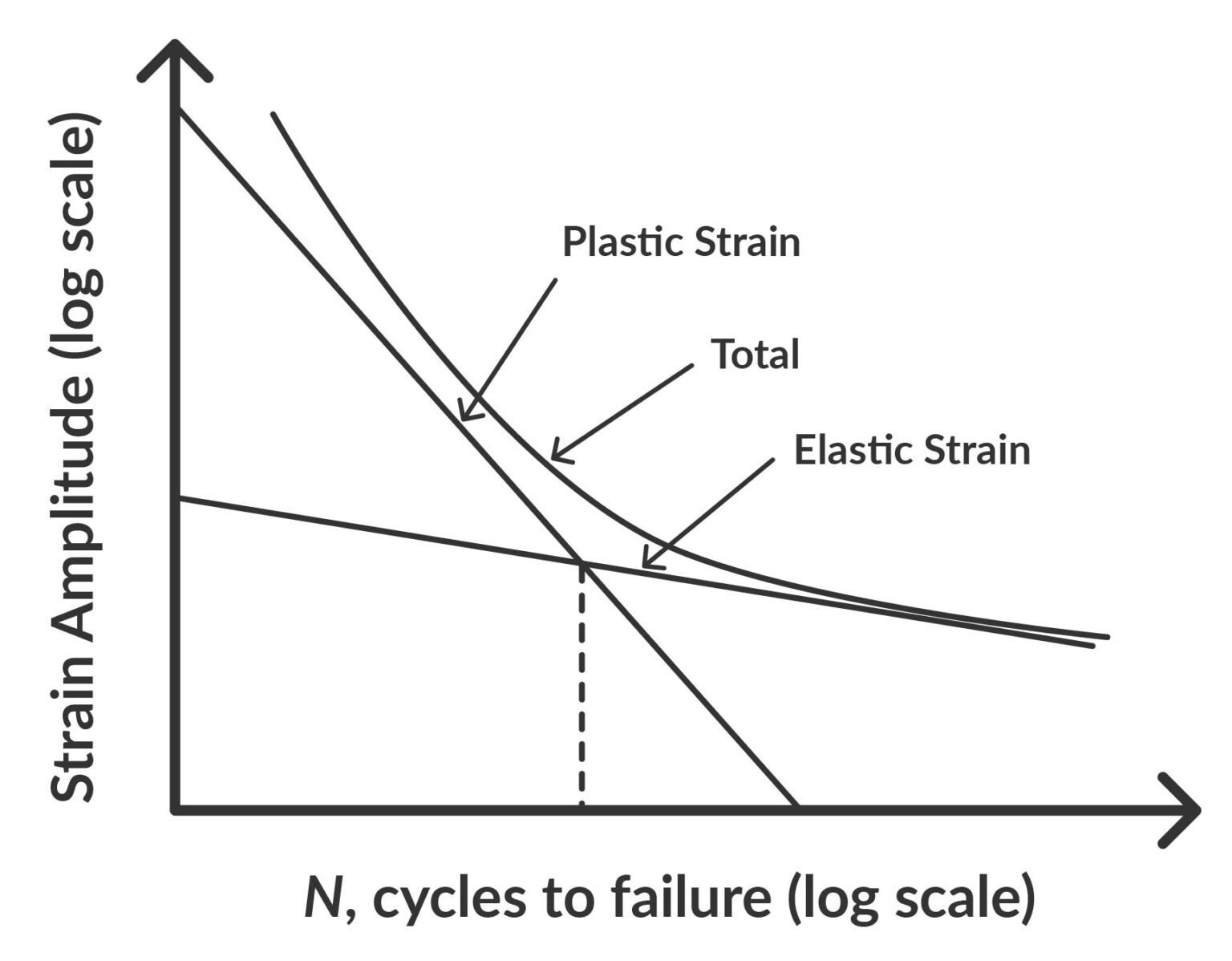
As shown in the Strain-Life curve (Figure 2), the total strain amplitude is composed of both elastic and plastic components.
Strain-Life (ε-N) curve illustrating the relationship between strain amplitude and cycles to failure, with the contributions of elastic and plastic strains. Image: simscale.com
It is beneficial in applications involving high-stress concentrations and large load fluctuations, such as automotive components like suspension systems and engine parts. In these cases, the materials must withstand substantial deformation due to constant acceleration, deceleration, and impact loads, making the Strain-Life method crucial for accurately predicting their fatigue life.
Fracture Mechanics Approach
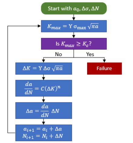
The fracture mechanics approach assesses fatigue behavior in welded structural components by analyzing fatigue crack propagation rate, material properties, and applied stress. It estimates the stress state at the crack tip using stress intensity factors, determining component damage tolerance. This method uses the stress intensity factor (K) and the crack growth rate (da/dN) to predict the remaining life of a component with an initial flaw.
It is applicable in critical structures where cracks are expected, such as aerospace components, pressure vessels, and welded structures. For example, in aircraft maintenance, the Fracture Mechanics approach helps predict the growth of fatigue cracks in the fuselage and wings, enabling timely inspections and repairs to prevent catastrophic failures.
Techniques in Fatigue Analysis for Structural Engineering
Understanding fatigue life and accurately predicting it involves using software tools, experimental methods, and analytical techniques. Each approach provides unique insights and complements the others to view a structure’s fatigue behavior comprehensively.
Software Tools
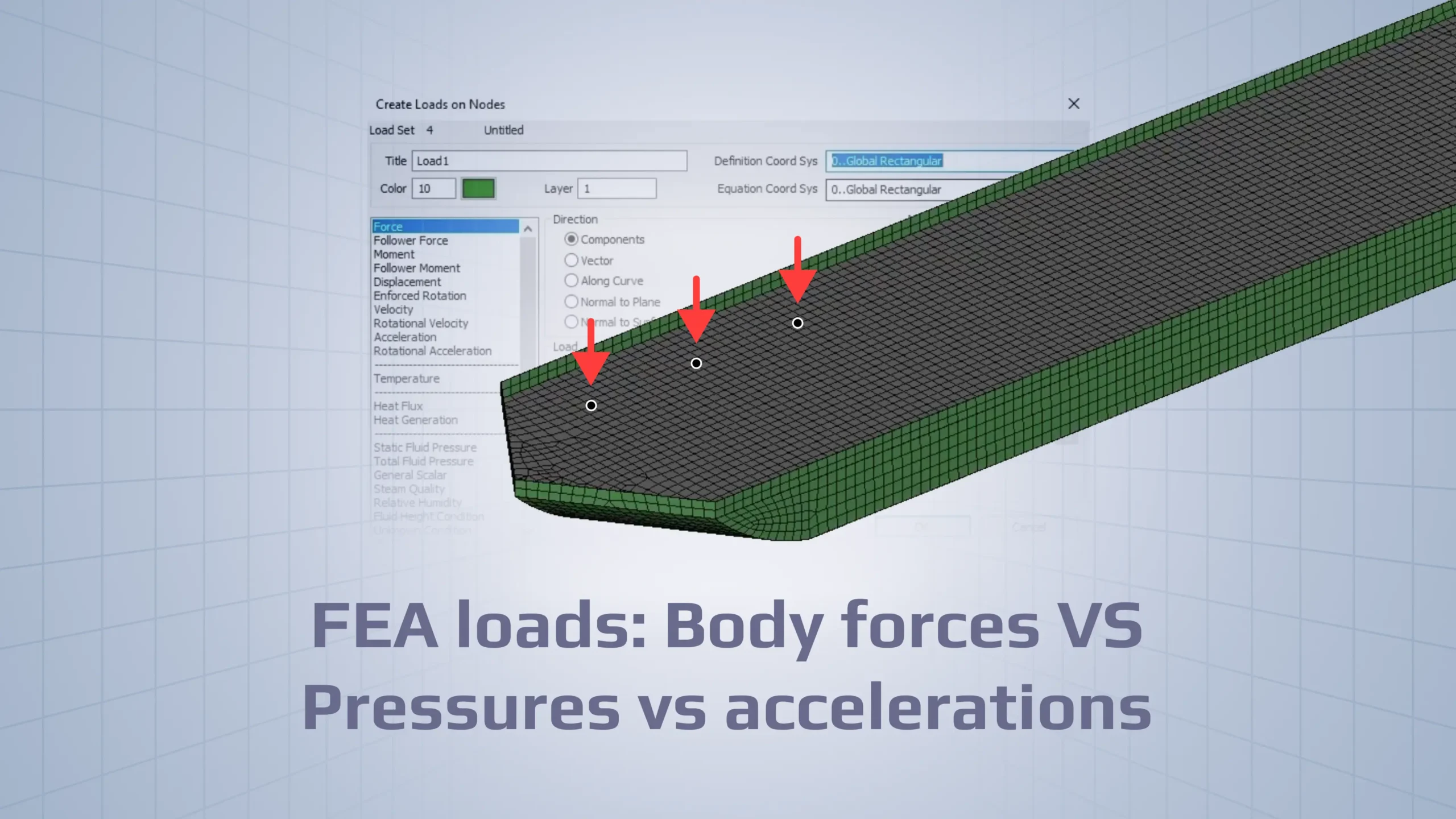
Finite Element Analysis (FEA) software tools simulate how structures respond to cyclic loads, helping predict potential fatigue failures.
Namely, SDC Verifier is a powerful all-in-one solution for structural design, FEA analysis, and verification according to industry standards. It can be used independently or in tandem with software like Ansys, Femap, and Simcenter 3D.
SDC Verifier automates the verification of FEA models against predefined industry standards, design codes, and user-defined criteria, streamlining the fatigue analysis process and ensuring accuracy.
Experimental Methods
Experimental methods involve physically testing materials and structures to observe their fatigue behavior under controlled conditions. These methods provide essential data for validating analytical models and ensuring the reliability of fatigue predictions. Examples of experimental methods include:
- Rotating Bending Test: This test subjects a cylindrical specimen to a rotating bending load, creating a cyclic stress distribution. It helps determine the material’s fatigue limit and the number of cycles to failure under bending conditions.
- Axial Fatigue Test: A specimen is subjected to repeated axial loads (tension-compression) to simulate real-world conditions where components experience direct pull and push forces. It measures the material’s response to fluctuating axial stresses.
- Crack Growth Testing: This method involves monitoring the growth of a preexisting crack in a material under cyclic loading. It helps understand the rate of crack propagation and the factors that influence it, such as stress intensity and environmental conditions.
- High-Frequency Resonance Testing: This technique applies cyclic loads at high frequencies to accelerate the fatigue testing process. It is beneficial for materials that require millions of cycles to reach fatigue failure, enabling quicker assessment of fatigue life.
- Thermal Fatigue Testing: Specimens are subjected to cyclic thermal loads to simulate conditions where materials experience repeated heating and cooling. This test is crucial for materials used in high-temperature applications, such as turbine blades and exhaust systems.
Analytical Methods
The Computer-Aided Engineering (CAE) approach to predicting fatigue life involves using numerical simulations to reduce development time and cost. Methods include Finite Element Method (FEM), Extended FEM, regular and complete spectral method, and standard and Extended Isogeometric Analysis (XIGA).
FEM is the most frequently used method due to its simple algorithm and ability to show stress-strain distribution. This approach clearly shows the stress-strain distribution and is the finest numerical simulation tool to tackle failure mechanic issues.
Conclusion
Detailed stages of fatigue failure — crack initiation, propagation, and final fracture — highlight the progression towards structural failure. Prediction methods such as the Stress-Life (S-N), Strain-Life, and Fracture Mechanics approach provide tailored insights for different scenarios.
Utilizing advanced fatigue analysis techniques, including software tools like SDC Verifier, experimental methods, and analytical techniques, enhances the accuracy and efficiency of fatigue assessments.

