How to Design and Use Below-the-Hook Lifting Devices According to ASME Standards
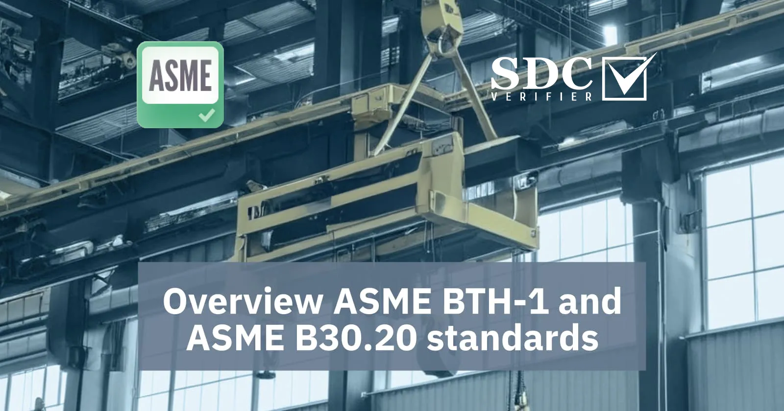
Below-the-hook lifting devices are tools that attach a load to a hoist, crane, or other lifting equipment. They can come in various forms, such as hooks, clamps, magnets, slings, and beams, and they are used for lifting, moving, and positioning loads of different shapes, sizes, and weights.
However, designing and using below-the-hook lifting devices is not a simple task. There are many factors to consider, such as the load characteristics, the lifting device components, the environmental conditions, and the safety requirements. That’s why it is important to follow the ASME standards that provide guidance and best practices for below-the-hook lifting devices.
In this article, we will introduce two ASME standards that are relevant for below-the-hook lifting devices: ASME BTH-1 and ASME B30.20. We will explain what they are, what they cover, and how they can help you design and use below-the-hook lifting devices more efficiently and safely.
What is ASME BTH-1?
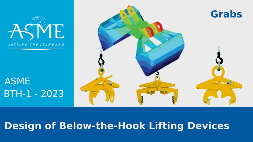
ASME BTH-1 is a standard that provides minimum structural, mechanical, and electrical design criteria for below-the-hook lifting devices. It applies to the design or modification of any device that is used for attaching a load to a hoist, such as structural and mechanical lifting devices, vacuum lifting devices, operated close proximity lifting magnets, remotely operated lifting magnets, or scrap and material handling grapples.
ASME BTH-1 does not replace ASME B30.20, which is another standard that addresses the safety requirements for below-the-hook lifting devices. ASME BTH-1 only covers the design aspects, while ASME B30.20 covers the marking, construction, installation, inspection, testing, maintenance, and operation of below-the-hook lifting devices.
ASME BTH-1 requires that lifting devices be designed by, or under the direct supervision of, a qualified person. It also specifies the rated load, load geometry, design category, and service class that must be considered during the design process. It provides formulas and methods for calculating the allowable stresses, materials, welding designs and procedures, and other design criteria.
The latest edition of ASME BTH-1 was published in 2023 and it includes some changes from the previous edition, such as:
- Clarification of requirements to establish the rated load of a lifting device by calculation
- Incorporation of ASME B30.30-2019 into rope requirements
- Additional requirements for the design and application of vacuum lifting devices
- Incorporation of ASME B30.1-2020 into the fluid power requirements
- Additional requirements added to address lifting attachments and load blocks
- Updated fatigue design parameters
Lifter Classifications of ASME BTH-1
One of the important aspects of ASME BTH-1 is the lifter classifications, which are used to determine the design criteria and the safety factors of the lifting devices. ASME BTH-1 defines four types of lifter classifications: design category, service class, load geometry factor, and rated load.
- Design category is a classification based on the probability of failure of the lifting device. It ranges from A to E, with A being the lowest and E being the highest. The design category depends on the consequences of failure, the reliability required, the inspection frequency, and the quality control. The higher the design category, the lower the allowable stress and the higher the safety factor of the lifting device.
- Service class is a classification based on the usage and loading of the lifting device. It ranges from 0 to 4, with 0 being the lowest and 4 being the highest. The service class depends on the number of load cycles, the load spectrum, the load duration, and the load frequency. The higher the service class, the lower the allowable stress and the higher the safety factor of the lifting device.
- Load geometry factor is a classification based on the shape and size of the load. It is calculated by dividing the maximum dimension of the load by the minimum dimension of the load. The load geometry factor affects the stability and the stress distribution of the lifting device. The higher the load geometry factor, the higher the allowable stress and the lower the safety factor of the lifting device.
- Rated load is the maximum load that the lifting device is designed to lift. It is established by the designer based on the load weight, the load geometry, the load balance, the load control, and the environmental factors. The rated load must not exceed the capacity of the hoist, crane, or other lifting equipment. The rated load must be clearly marked on the lifting device.
The following table shows the design criteria and the safety factors for different lifter classifications according to ASME BTH-1-2023:
Click to reveal the table
|
Design Category |
Service Class |
Load Geometry Factor |
Allowable Stress |
Safety Factor |
|
A |
0 |
1 |
0.75 Fy |
1.33 |
|
A |
0 |
2 |
0.50 Fy |
2.00 |
|
A |
0 |
3 |
0.38 Fy |
2.63 |
|
A |
0 |
4 |
0.30 Fy |
3.33 |
|
A |
1 |
1 |
0.60 Fy |
1.67 |
|
A |
1 |
2 |
0.40 Fy |
2.50 |
|
A |
1 |
3 |
0.30 Fy |
3.33 |
|
A |
1 |
4 |
0.24 Fy |
4.17 |
|
A |
2 |
1 |
0.50 Fy |
2.00 |
|
A |
2 |
2 |
0.33 Fy |
3.00 |
|
A |
2 |
3 |
0.25 Fy |
4.00 |
|
A |
2 |
4 |
0.20 Fy |
5.00 |
|
A |
3 |
1 |
0.40 Fy |
2.50 |
|
A |
3 |
2 |
0.27 Fy |
3.70 |
|
A |
3 |
3 |
0.20 Fy |
5.00 |
|
A |
3 |
4 |
0.16 Fy |
6.25 |
|
A |
4 |
1 |
0.33 Fy |
3.00 |
|
A |
4 |
2 |
0.22 Fy |
4.55 |
|
A |
4 |
3 |
0.17 Fy |
5.88 |
|
A |
4 |
4 |
0.13 Fy |
7.69 |
|
B |
0 |
1 |
0.60 Fy |
1.67 |
|
B |
0 |
2 |
0.40 Fy |
2.50 |
|
B |
0 |
3 |
0.30 Fy |
3.33 |
|
B |
0 |
4 |
0.24 Fy |
4.17 |
|
B |
1 |
1 |
0.50 Fy |
2.00 |
|
B |
1 |
2 |
0.33 Fy |
3.00 |
|
B |
1 |
3 |
0.25 Fy |
4.00 |
|
B |
1 |
4 |
0.20 Fy |
5.00 |
|
B |
2 |
1 |
0.40 Fy |
2.50 |
|
B |
2 |
2 |
0.27 Fy |
3.70 |
|
B |
2 |
3 |
0.20 Fy |
5.00 |
|
B |
2 |
4 |
0.16 Fy |
6.25 |
|
B |
3 |
1 |
0.33 Fy |
3.00 |
|
B |
3 |
2 |
0.22 Fy |
4.55 |
|
B |
3 |
3 |
0.17 Fy |
5.88 |
|
B |
3 |
4 |
0.13 Fy |
7.69 |
|
B |
4 |
1 |
0.27 Fy |
3.70 |
|
B |
4 |
2 |
0.18 Fy |
5.56 |
|
B |
4 |
3 |
0.13 Fy |
7.69 |
|
B |
4 |
4 |
0.10 Fy |
10.00 |
|
C |
0 |
1 |
0.50 Fy |
2.00 |
|
C |
0 |
2 |
0.33 Fy |
3.00 |
|
C |
0 |
3 |
0.25 Fy |
4.00 |
|
C |
0 |
4 |
0.20 Fy |
5.00 |
|
C |
1 |
1 |
0.40 Fy |
2.50 |
|
C |
1 |
2 |
0.27 Fy |
3.70 |
|
C |
1 |
3 |
0.20 Fy |
5.00 |
|
C |
1 |
4 |
0.16 Fy |
6.25 |
|
C |
2 |
1 |
0.33 Fy |
3.00 |
|
C |
2 |
2 |
0.22 Fy |
4.55 |
|
C |
2 |
3 |
0.17 Fy |
5.88 |
|
C |
2 |
4 |
0.13 Fy |
7.69 |
|
C |
3 |
1 |
0.27 Fy |
3.70 |
|
C |
3 |
2 |
0.18 Fy |
5.56 |
|
C |
3 |
3 |
0.14 Fy |
7.14 |
|
C |
3 |
4 |
0.11 Fy |
9.09 |
|
C |
4 |
1 |
0.22 Fy |
4.55 |
|
C |
4 |
2 |
0.15 Fy |
6.67 |
|
C |
4 |
3 |
0.11 Fy |
9.09 |
|
C |
4 |
4 |
0.09 Fy |
11.11 |
|
D |
0 |
1 |
0.40 Fy |
2.50 |
|
D |
0 |
2 |
0.27 Fy |
3.70 |
|
D |
0 |
3 |
0.20 Fy |
5.00 |
|
D |
0 |
4 |
0.16 Fy |
6.25 |
|
D |
1 |
1 |
0.33 Fy |
3.00 |
|
D |
1 |
2 |
0.22 Fy |
4.55 |
|
D |
1 |
3 |
0.17 Fy |
5.88 |
|
D |
1 |
4 |
0.13 Fy |
7.69 |
|
D |
2 |
1 |
0.27 Fy |
3.70 |
|
D |
2 |
2 |
0.18 Fy |
5.56 |
|
D |
2 |
3 |
0.14 Fy |
7.14 |
|
D |
2 |
4 |
0.11 Fy |
9.09 |
|
D |
3 |
1 |
0.22 Fy |
4.55 |
|
D |
3 |
2 |
0.15 Fy |
6.67 |
|
D |
3 |
3 |
0.11 Fy |
9.09 |
|
D |
3 |
4 |
0.09 Fy |
11.11 |
|
D |
4 |
1 |
0.18 Fy |
5.56 |
|
D |
4 |
2 |
0.12 Fy |
8.33 |
|
D |
4 |
3 |
0.09 Fy |
11.11 |
|
D |
4 |
4 |
0.07 Fy |
14.29 |
|
E |
0 |
1 |
0.33 Fy |
3.00 |
|
E |
0 |
2 |
0.22 Fy |
4.55 |
|
E |
0 |
3 |
0.17 Fy |
5.88 |
|
E |
0 |
4 |
0.13 Fy |
7.69 |
|
E |
1 |
1 |
0.27 Fy |
3.70 |
|
E |
1 |
2 |
0.18 Fy |
5.56 |
|
E |
1 |
3 |
0.14 Fy |
7.14 |
|
E |
1 |
4 |
0.11 Fy |
9.09 |
|
E |
2 |
1 |
0.22 Fy |
4.55 |
|
E |
2 |
2 |
0.15 Fy |
6.67 |
|
E |
2 |
3 |
0.11 Fy |
9.09 |
|
E |
2 |
4 |
0.09 Fy |
11.11 |
|
E |
3 |
1 |
0.18 Fy |
5.56 |
|
E |
3 |
2 |
0.12 Fy |
8.33 |
|
E |
3 |
3 |
0.09 Fy |
11.11 |
|
E |
3 |
4 |
0.07 Fy |
14.29 |
|
E |
4 |
1 |
0.15 Fy |
6.67 |
|
E |
4 |
2 |
0.10 Fy |
10.00 |
|
E |
4 |
3 |
0.08 Fy |
12.50 |
|
E |
4 |
4 |
0.06 Fy |
16.67 |
where Fy is the minimum specified yield strength of the material.
Example
Assume you’re designing a lifter for a critical (Category A) manufacturing component. For occasional use (Service Class 0), a Load Geometry Factor of 1 applies. Your material has a yield strength (Fy) of 50,000 psi.
Your calculations would look like this:
- Allowable Stress: 0.75 * 50,000 = 37,500 psi
- Safety Factor: 1.33
This means you design the lifter so that the maximum expected stress it could ever experience in service never exceeds 37,500 psi, giving you a safety factor of 1.33 times the anticipated loads.
What is ASME B30.20?
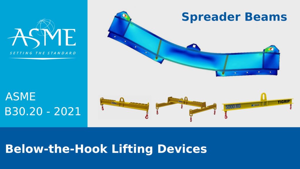
ASME B30.20 is a standard that provides safety requirements for below-the-hook lifting devices. It applies to the marking, construction, installation, inspection, testing, maintenance, and operation of any device that is used for attaching a load to a hoist, such as structural and mechanical lifting devices, vacuum lifting devices, operated close proximity lifting magnets, remotely operated lifting magnets, or scrap and material handling grapples. It also applies to clamps used for positioning and anchoring.
ASME B30.20 is part of the ASME B30 series, which is a collection of standards that cover various aspects of cableways, cranes, derricks, hoists, hooks, jacks, and slings. ASME B30.20 is intended to complement ASME BTH-1, which is another standard that covers the design criteria for below-the-hook lifting devices. ASME B30.20 focuses on the safety aspects, while ASME BTH-1 focuses on the design aspects.
ASME B30.20 requires that lifting devices be operated by a qualified person.
It also specifies the marking, inspection, testing, and maintenance procedures that must be followed to ensure the safe performance of the lifting devices. It provides guidelines and precautions for the proper use and handling of the lifting devices, such as the load rating, the load balance, the load control, and the environmental factors.
The latest edition of ASME B30.20 was published in 2021 and it includes some changes from the previous edition, such as:
- Revisions to load test requirements
- Clarification of frequent and periodic inspection requirements
- Criteria for the removal of a lifting device from service if certain conditions that could result in unsafe performance are present, such as loose or missing guards or fasteners, indications of heat damage, excessive corrosion, or deformation, cracks, or wear
Safety Requirements of ASME B30.20
One of the important aspects of ASME B30.20 is the safety requirements, which are used to ensure the safe performance and operation of the lifting devices. ASME B30.20 defines four types of safety requirements: marking, inspection, testing, and maintenance.
- Marking is the process of applying identification and information labels to the lifting device and its components. The marking must include the name and trademark of the manufacturer, the rated load, the serial number, the weight of the device, and any other relevant data or warnings. The marking must be legible, durable, and visible to the operator and the inspector.
- Inspection is the process of examining the lifting device and its components for any defects, damage, or wear that could affect its performance or safety. The inspection must be performed by a qualified person at regular intervals, depending on the frequency and severity of use. The inspection must follow the procedures and criteria specified by the manufacturer and the standard. The inspection results must be recorded and reported to the responsible authority.
- Testing is the process of verifying the capacity and functionality of the lifting device and its components. The testing must be performed by a qualified person before the initial use, after any repair or modification, and whenever deemed necessary by the inspector. The testing must follow the procedures and criteria specified by the manufacturer and the standard. The testing results must be recorded and reported to the responsible authority.
- Maintenance is the process of repairing, adjusting, cleaning, lubricating, and replacing the lifting device and its components. The maintenance must be performed by a qualified person as required by the inspection and testing results, the manufacturer’s recommendations, and the standard. The maintenance must follow the procedures and criteria specified by the manufacturer and the standard. The maintenance records must be kept and updated.
How Can SDC Verifier Help You Comply with ASME Standards?
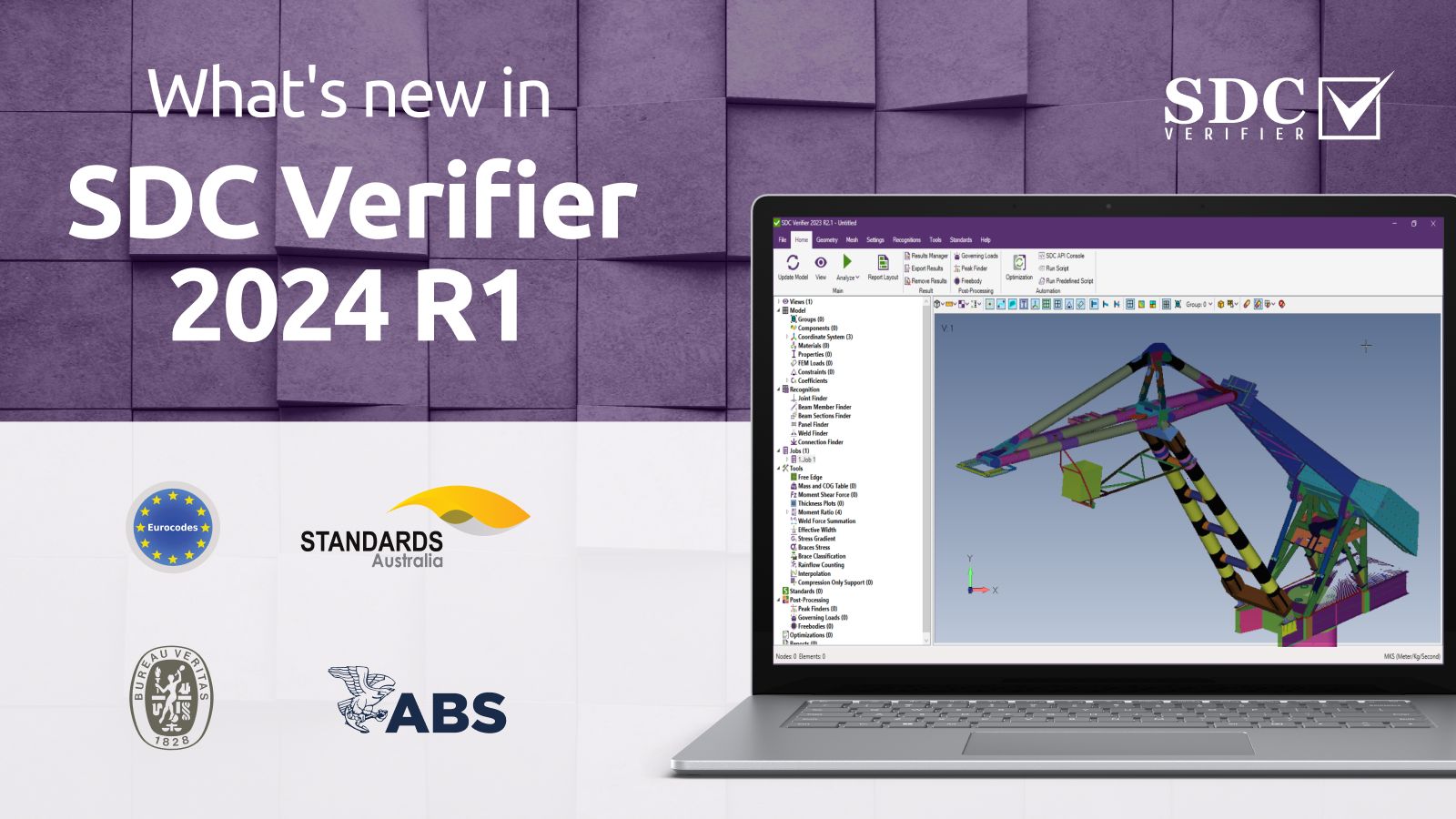
SDC Verifier is a software and consultancy firm that provides advanced simulation and standard verification solutions for structural engineering. Our software, SDC Verifier, is a powerful tool that can help you design and verify according to various standards.
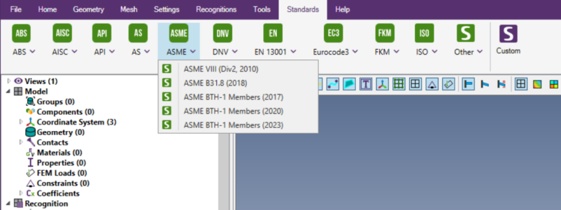
Currently, in SDC Verifier, it is possible to perform code checking according to five ASME standards:
- ASME Section VIII, Division 2, 2010 – Design for longitudinal stress check. Section 8 is dedicated to pressure vessels.
- ASME B31.8-2018 (Gas Transmission and Distribution Piping Systems)
- ASME BTH-1 – Below-the-Hook Lifting Devices (2017, 2020, 2023)
SDC Verifier can help you save time and money by automating and streamlining the design and verification process. You can also benefit from our expertise and experience in structural engineering and standard verification.
Contact SDC Verifier’s Engineering team, and we will help you solve your problem. See all FEA consultancy services SDC Verifier can provide.
Learn more about engineering FEA projects SDC Verifier Engineering Department complete for our clients in different industries.
Conclusion
Below-the-hook lifting devices are essential tools for lifting, moving, and positioning loads of different shapes, sizes, and weights. However, they also pose significant challenges and risks for the designers and users of these devices. That’s why it is important to follow the ASME standards that provide guidance and best practices for below-the-hook lifting devices.
ASME BTH-1 and ASME B30.20 are two standards that cover the design and safety requirements for below-the-hook lifting devices. They provide minimum criteria and recommendations for the structural, mechanical, and electrical design, as well as the marking, construction, installation, inspection, testing, maintenance, and operation of below-the-hook lifting devices.
