BV NR615: The Ultimate Guide to Buckling Assessment of Plated Structures

A single miscalculation in plate buckling assessment can jeopardize an entire engineering project, leading to catastrophic failures and costly delays. Did you know that up from 20% to 40% of structural failures in marine and offshore applications can be attributed to buckling? BV NR 615 provides the framework to avoid such disasters, and SDC Verifier empowers engineers to implement it with precision and efficiency.
Understanding BV NR615 Fundamentals
BV NR615 establishes a structured approach to evaluate the buckling strength of plated structures, ensuring their ability to withstand compressive and shear stresses under various loading scenarios. Central to this assessment is the concept of the buckling utilization factor (η), a dimensionless ratio that quantifies the relationship between applied loads and the structure’s ultimate buckling capacity.
The buckling utilization factor is defined as:
Where:
- η_act is the actual buckling utilization factor under applied loads.
- W_act is the equivalent applied stress.
- W_u is the equivalent buckling capacity.
- γ_c is the stress multiplier factor at failure.
To ensure structural safety, BV NR615 introduces the concept of an allowable buckling utilization factor (η_all). This factor, specified in the applicable rules, represents the maximum permissible value of η_act for a given structural element. The buckling acceptance criterion mandates that η_act must not exceed η_all, ensuring that the applied loads do not compromise the structure’s buckling strength.
BV NR615 recognizes that buckling behavior can vary significantly depending on the boundary conditions of the plated structure. To address this, the standard defines two assessment methods:
- Method A: Assumes that all edges of the elementary plate panel are forced to remain straight due to the surrounding structure, providing strong in-plane support. This method is typically applicable to plates integrated into larger assemblies, such as bulkheads supported by girders.
- Method B: Considers scenarios where the edges of the elementary plate panel are not forced to remain straight due to low in-plane stiffness or the absence of surrounding support. This method is often relevant for plates with weaker edge constraints, such as unsupported girder webs.
Implementing BV NR615 in SDC Verifier
Within SDC Verifier, activating the BV NR615 standard is a straightforward process. From the ribbon, navigate to Standards - Main - Other and select BV NR615 Plate Buckling (2023). This action seamlessly integrates the standard’s requirements into your analysis workflow.
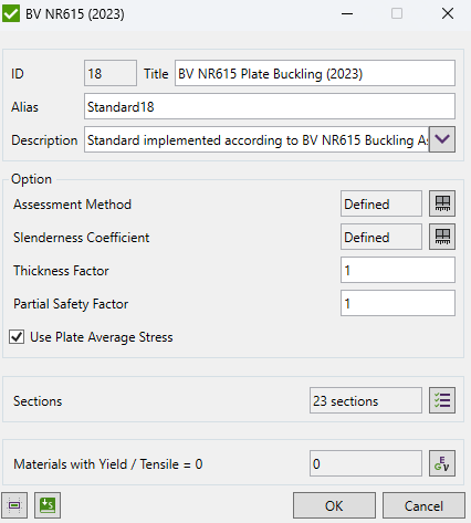
Image of the BV NR615 activation window in SDC Verifier
A fundamental concept in BV NR615 is the definition of “Sections.” Sections are discrete portions of the plated structure that are assessed for buckling independently. They are typically defined by boundaries such as bulkheads, web frames, or other structural discontinuities. By dividing the structure into sections, engineers can focus their analysis on specific areas of interest, optimizing computational resources and ensuring a targeted assessment.
SDC Verifier’s Panel Finder tool is a powerful asset in this process. It automatically identifies individual plate panels within each section, extracting their dimensions and properties. This automation eliminates the need for manual measurement and data entry, significantly reducing the potential for human error and accelerating the analysis setup. The Panel Finder tool’s ability to intelligently recognize complex panel geometries, including those with varying thicknesses or irregular shapes, further enhances its utility for real-world engineering applications.
Customizing Assessment Parameters
SDC Verifier empowers engineers with a range of customizable parameters to fine-tune the buckling assessment process, aligning it with specific project requirements and design considerations. The accuracy of these assessments hinges on precise material data, particularly yield and tensile strengths. The software’s integrated wizard plays a crucial role in verifying the completeness of this data, ensuring that all necessary material properties are defined for the analysis.
Let’s delve into the key customizable parameters available in SDC Verifier:
- Assessment Method: This parameter allows engineers to choose between two distinct methodologies outlined in Appendix 2 of BV NR615. The choice between Method A (edges forced to remain straight) and Method B (edges not forced to remain straight) depends on the specific boundary conditions and constraints of the plated structure under consideration. Selecting the appropriate method is essential for accurately capturing the buckling behavior and ensuring compliance with the standard.
- Slenderness Coefficient (C): This coefficient, as defined in Section 2.1 of BV NR615, is a critical factor in determining the minimum net thickness requirements for plate panels. It accounts for the structural configuration and intended application, with different values prescribed for the hull envelope (C = 100) and other structures (C = 125). Adjusting this coefficient directly impacts the allowable plate thickness, influencing material selection and overall structural weight.

The net thickness of the plate panel criterion, where t_p is the net thickness, C is the slenderness coefficient, and R_eH is the specified minimum yield stress of the material. The slenderness coefficient is set to 100 for the hull envelope and 125 for other structures.
- Thickness Factor: This factor provides engineers with the flexibility to increase the effective thickness of plate panels in the analysis. By doing so, the calculated stresses are reduced, providing an additional margin of safety against buckling. This parameter can be particularly useful in scenarios where uncertainties exist regarding material properties, loading conditions, or fabrication tolerances.
- Partial Safety Factor (S): BV NR615 specifies different partial safety factors based on the specific application and loading conditions of the structure. These factors account for uncertainties in material properties, structural behavior, and load modeling. SDC Verifier allows engineers to select the appropriate partial safety factor as per Section 5 of the standard, ensuring that the analysis adheres to the prescribed safety levels.
A partial safety factor of 1.1 is applied to structures exposed to local concentrated loads, while a factor of 1.15 is used for stiffeners in specific locations of ships carrying dry cargo in bulk. For all other cases, a factor of 1.0 is applied.
- Use Plate Average Stress: This option determines whether the analysis utilizes the average stress across the entire plate or the averaged stress on the plate using element areas. The choice between these two approaches can influence the accuracy of stress calculations, particularly for plates with complex geometries or varying stress distributions.

When the ‘Use Plate Average Stress’ option is turned ON, a single buckling factor is calculated for the entire plate based on the weighted average of stresses across the elements. Conversely, when turned OFF, the buckling factor is calculated individually for each element, and the maximum value is taken as the plate buckling factor.
By judiciously adjusting these parameters, engineers can tailor the buckling assessment to the unique characteristics of their projects.
Interpreting Plate Buckling Results
SDC Verifier presents plate buckling results in multiple formats, catering to different analysis and reporting needs:
- Criteria Plot: This graphical representation provides a comprehensive overview of the buckling assessment, plotting utilization factors against various criteria. It allows engineers to quickly identify critical areas and assess the overall buckling performance of the structure.
- Table (Expand/Extreme): This tabular format offers detailed numerical results for each plate panel and stiffener. The “Expand” option provides a comprehensive list of results, while the “Extreme” option filters the results to display only the most critical values, aiding in pinpointing areas that require immediate attention.
- Flow Table (Over Loads): This table presents the utilization factors for each load case, allowing engineers to assess the impact of different loading scenarios on the buckling behavior of the structure. It helps identify the most critical load combinations and guides design modifications to ensure adequate safety margins.
A crucial aspect of plate buckling checks is stress conversion. Finite element analysis (FEA) typically calculates stresses in the element’s local coordinate system. However, BV NR615 requires these stresses to be translated into the plate’s global X, Y, and XY directions for accurate assessment. This conversion is essential because the buckling behavior of a plate is direction-dependent, and misalignment of stresses can lead to erroneous results.
SDC Verifier automates this stress conversion process, simplifying the analysis workflow for engineers. The software assumes that plate elements are calculated without output transformation and uses default orientations for stress directions:
- Triangle Elements: The x-stress is oriented along the first edge (defined by node1 to node2).
- Quad Elements: The x-stress is oriented along the diagonal bisector of the element.
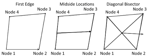
For triangle elements, the x-stress is assumed to be oriented along the first edge (from node 1 to node 2). For quad elements, the x-stress is assumed to be oriented along the diagonal bisector of the element.
Plate Dimensions and Thickness Considerations
Accurate determination of plate dimensions and thickness is fundamental to reliable plate buckling assessments. SDC Verifier’s Panel Finder tool simplifies this process by automatically identifying the longest edge of a plate as its length and the longest perpendicular edge as its width. This intuitive approach ensures a consistent and geometrically accurate representation of the plate’s dimensions, regardless of its orientation within the structure.
However, not all plate geometries are perfectly rectangular. In cases where plates exhibit irregular shapes, the Common Structural Rules (CSR) method, as outlined in Part 1, Chapter 8, Section 4 (2.3) of the CSR, provides a standardized approach for calculating equivalent rectangular plate dimensions. This method enables engineers to apply BV NR615’s buckling assessment criteria to complex geometries, ensuring a comprehensive evaluation of structural integrity.
Within SDC Verifier, the thickness of each plate element is directly extracted from the finite element model. This element-level thickness data is then utilized in the buckling calculations, capturing the variations in thickness that may exist across the plate. For specialized scenarios where a uniform thickness assumption is desired, the software offers the option for manual thickness input. This flexibility allows engineers to override the element-level data and specify a constant thickness for the entire plate, simplifying the analysis or addressing specific design considerations.

A plate with two different thicknesses (0.01 and 0.02) will have varying buckling behaviors across its surface. The left image shows the element thickness distribution, while the right image displays the corresponding buckling factor plot. The thicker region (0.02) exhibits a higher buckling resistance (lower buckling factor) compared to the thinner region (0.01). This highlights the importance of accurately capturing thickness variations in the analysis for reliable buckling assessments.
The impact of varying plate thicknesses on buckling behavior is significant. Thicker plates generally exhibit higher buckling resistance due to increased stiffness. Conversely, thinner plates are more susceptible to buckling under compressive loads.
Finite Element Analysis (FEA) Requirements
BV NR615 provides explicit guidance on modeling requirements for Finite Element Analysis (FEA) to ensure accurate buckling assessments.
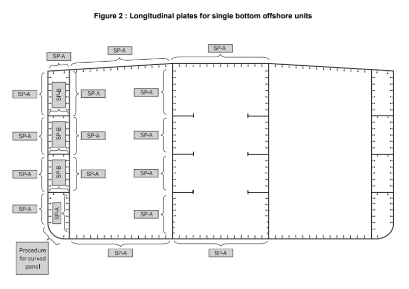
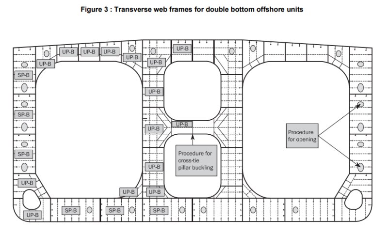
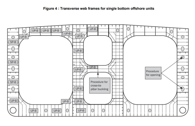
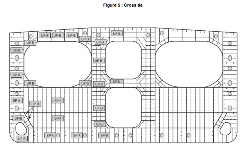
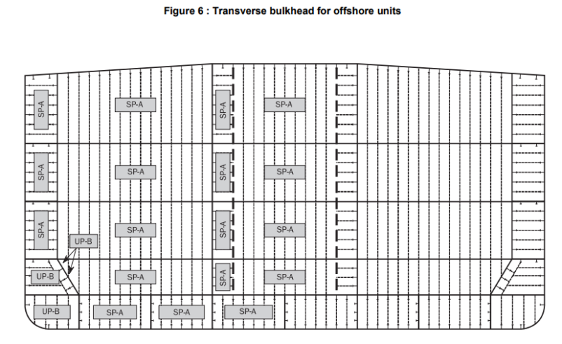
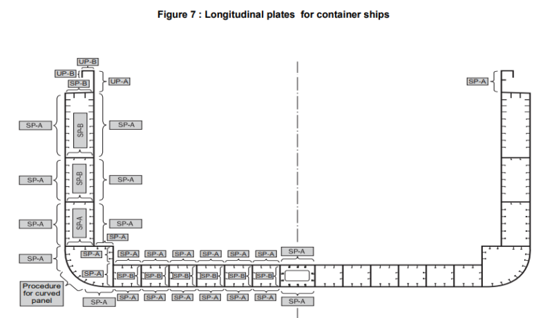
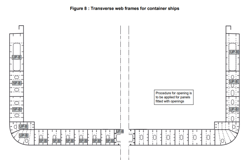
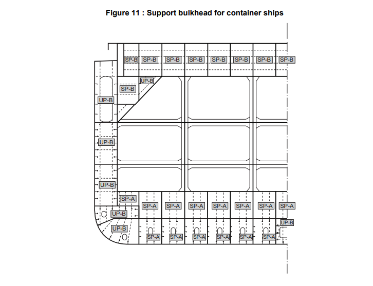
- Structural Elements: The standard mandates that all structural elements within the FEA model be assessed individually. This includes stiffened and unstiffened panels (even curved ones), web plates with openings, corrugated bulkheads, vertically stiffened side shells (common in single-side skin ships), struts, pillars, and cross ties. Each element’s buckling behavior is unique, necessitating individual scrutiny to capture potential failure modes accurately.
-
Modeling Irregular and Triangular Unstiffened Panels
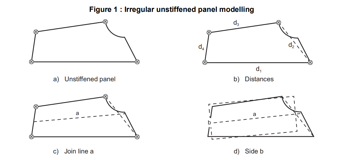
For unstiffened panels with irregular shapes, BV NR615 provides guidelines for determining equivalent rectangular plate dimensions. This process involves identifying reference points and measuring distances as illustrated belov. These equivalent dimensions are then used in the buckling assessment calculations.
Irregular unstiffened panel modeling, showing the identification of reference points and measurement of distances for determining equivalent rectangular plate dimensions.
Triangular unstiffened panel modeling, illustrating the determination of the longest median (l1) and width (l2) of the model for buckling assessment calculations.
-
- Mesh Refinement: Mesh refinement is crucial for precise stress calculations, especially in regions with high stress gradients. BV NR615 does not explicitly define mesh density requirements, but it implicitly emphasizes the need for a mesh fine enough to capture stress variations accurately. Engineers should employ a mesh convergence study to determine the optimal mesh density that balances accuracy with computational efficiency.
- Boundary Conditions and Load Application: Accurately simulating real-world buckling scenarios requires careful consideration of boundary conditions and load application. BV NR615 recommends modeling plate panels as either stiffened or unstiffened, with the choice between Method A (strong in-plane support) and Method B (weak in-plane support) depending on the specific constraints of the structure. The applied loads, including compressive stresses, shear stresses, and lateral pressure, should be representative of the expected operating conditions.
- Interpreting FEA Results: Post-processing FEA results involves extracting relevant data, such as stress distributions, buckling modes, and utilization factors. These results are then interpreted in the context of BV NR615 compliance. For instance, the calculated buckling utilization factor (η) for each element should not exceed the allowable buckling utilization factor (η_all) specified in the standard. Any exceedance indicates a potential buckling risk that needs to be addressed through design modifications or reinforcement.
Stress-Based Reference Stresses
BV NR615 introduces the concept of stress-based reference stresses as a practical methodology to address this challenge. This approach leverages the actual stress data obtained from finite element analysis (FEA) or other numerical methods to derive representative stress values along the panel boundaries.
For regular panels (those with rectangular shapes), the stress-based method involves fitting a 2nd-order polynomial curve to the longitudinal stress (σx) distribution along the shorter edge. This curve is determined using the least-squares method, with the area of each element serving as a weighting factor. The peak values of this curve, along with the average stress, are then used as reference stresses for the buckling assessment. The transverse stress (σy) along the longer edges is calculated by extrapolating the transverse stresses of all elements up to the shorter edges, assuming a linear distribution.
For irregular and curved panels, a weighted average approach is employed to calculate the reference stresses. The longitudinal, transverse, and shear stresses are averaged across the panel, with each element’s stress weighted by its area. This approach provides a simplified yet effective way to account for the complex stress distributions often encountered in irregular geometries.
The stress-based reference stress method offers several advantages for accurate buckling assessments. By utilizing actual stress data from the analysis, it captures the nuances of the stress distribution, leading to more realistic and reliable results. This is particularly crucial for irregular and curved panels, where stress concentrations and variations can significantly impact buckling behavior. Additionally, the method’s flexibility allows it to be applied to a wide range of panel geometries and loading conditions, making it a valuable tool in the engineer’s arsenal.
Method Selection for Direct Strength Analysis
BV NR615, Appendix 2, provides a framework for this selection, primarily focusing on two methods: Method A and Method B.
Method A is suitable for plate panels with edges that are constrained to remain straight due to the surrounding structure. This typically applies to panels integrated into larger assemblies, such as bulkheads supported by longitudinal girders. The inherent rigidity of the surrounding structure provides substantial in-plane support, preventing the edges from rotating or deflecting significantly.
Conversely, Method B is applicable when the edges of the plate panel are not forced to remain straight. This scenario often arises in panels with weaker edge constraints or those not integrated into larger assemblies. Examples include unsupported girder webs or panels with large openings.
Several factors influence the choice between Method A and Method B:
- Panel Geometry: The shape and dimensions of the panel play a crucial role. Regular, rectangular panels, as depicted on the left side of the figure, are often amenable to Method A due to their inherent symmetry and well-defined boundary conditions. Conversely, irregular or complex geometries, such as the triangular panel shown on the right, may necessitate Method B to accurately capture the buckling behavior, as the uneven stress distribution and varying edge constraints can lead to complex buckling modes not easily predicted by simpler models.
Impact of panel geometry on buckling behavior
- Boundary Conditions: The degree of rotational and translational restraint at the panel edges is a key determinant. If the edges are effectively clamped or simply supported, Method A may be appropriate. However, if the edges are free or have limited restraint, Method B is often the preferred choice.
- Loading Conditions: The nature and distribution of applied loads can influence the buckling mode and, consequently, the appropriate modeling method. For instance, panels subjected to predominantly compressive loads may behave differently than those under combined compression and shear.
To optimize analysis efficiency while ensuring compliance with BV NR615, consider the following practical tips:
- Leverage SDC Verifier’s Panel Finder Tool: This tool automates the identification of plate panels and their properties, streamlining the modeling process and reducing the risk of manual errors.
- Consult Appendix 2 of BV NR615: This appendix provides a comprehensive table outlining the recommended assessment methods for various structural elements, serving as a valuable reference for engineers.
- Perform Sensitivity Studies: If uncertainties exist regarding boundary conditions or loading scenarios, conduct sensitivity studies to assess the impact of different modeling assumptions on the results.
- Validate with Physical Testing (if feasible): In critical applications, consider validating the numerical results with physical testing to ensure the accuracy of the buckling assessment.
Design Optimization for Buckling Compliance
SDC Verifier is not merely a compliance tool; it’s a powerful ally in the quest for design optimization. By harnessing its capabilities, engineers can iteratively refine their plated structures to achieve optimal buckling performance, striking a balance between safety, weight, and cost-effectiveness.
Parametric Studies: SDC Verifier allows engineers to systematically vary key design parameters, such as plate thickness, stiffener dimensions, and material properties, while observing the resulting impact on buckling utilization factors. This iterative process helps identify the most influential parameters and their optimal values for achieving compliance with BV NR615.
Sensitivity Analyses: By quantifying the sensitivity of buckling behavior to changes in design parameters, engineers can gain valuable insights into the robustness of their designs. This information is crucial for making informed decisions about material selection, structural layout, and reinforcement strategies.
Automated Optimization Routines: SDC Verifier’s optimization algorithms can automatically explore the design space, seeking configurations that minimize weight or cost while satisfying the buckling criteria of BV NR615. This automation not only accelerates the optimization process but also uncovers non-intuitive design solutions that may not be apparent through manual iteration.
Real-World Impact: The benefits of design optimization are tangible. By strategically adjusting plate thicknesses and stiffener dimensions, engineers can achieve significant material savings and weight reduction without compromising structural integrity. This translates to reduced material costs, improved fuel efficiency for marine vessels, and enhanced overall performance for offshore structures.
For instance, in the design of a ship’s hull, optimizing the plate thickness distribution can lead to substantial weight savings, directly impacting the vessel’s payload capacity and fuel consumption. Similarly, optimizing the stiffener layout in an offshore platform can reduce material usage and construction costs while maintaining the required strength and stability.
By embracing SDC Verifier’s design optimization capabilities, engineers can transcend the limitations of traditional trial-and-error approaches and unlock the full potential of their plated structures. This not only ensures compliance with BV NR615 but also paves the way for innovative, efficient, and cost-effective engineering solutions.


