ASD (Allowable Stress Design) and LRFD (Load and Resistance Factor Design) are structural engineering methodologies used to ensure safety and reliability. ASD (or Working Stress Design) is an earlier approach based on keeping stresses below allowable limits. LRFD (or Limit State Design) is a later, reliability-based method that compares factored loads with reduced member resistance. By explicitly accounting for uncertainties, LRFD has become the dominant approach in most modern design codes and standards.
In an FEA workflow, ASD vs LRFD is usually not about changing the mesh or solver. The same FE model may be used, but the verification setup changes: load combinations, factors, allowable limits, resistance factors, and utilization criteria must match the selected design method.
What is ASD?
ASD checks whether the required demand in a structural member obtained under load combinations remains below an allowable limit defined by the governing standard. The safety margin is generally introduced through an allowable stress, allowable strength, or nominal resistance reduced by a safety factor.
The factor of safety accounts for uncertainties in material properties, loading conditions, fabrication tolerances, and structural behavior that may affect overall structural performance. This approach provides a direct relationship between demand and allowable capacity. ASD or WSD formats remain relevant where they are required by the governing standard, project specification, or established engineering practice.
Allowable Stress Design vs Allowable Strength Design
Traditionally, ASD stands for Allowable Stress Design, which focuses on keeping working stresses below allowable stress limits. However, in modern AISC steel design terminology, ASD is also referred to as Allowable Strength Design. While the terminology differs, both approaches follow the same fundamental principle: the allowable capacity of a structural member is determined by reducing the nominal resistance, allowable stress, or code-defined capacity using a safety factor.
In practice, both terms are widely used in engineering literature and steel design standards, especially in structural and finite element analysis applications.
ASD Formula: Allowable Stress and Allowable Strength
The design equation of the ASD method can be expressed as:
where σi is a working stress due to the design load, which is determined by an elastic structural analysis under the design loading conditions. σall is the allowable stress of the constructional material. The σn is the nominal stress of the material, and FS denotes the safety factor specified in the design specification.
For an AISC-style allowable strength check, the same idea is commonly expressed as:
\[R_u \leq \frac{R_n}{\Omega}\]
ASD Load Factors and Factor of Safety
In ASD, the primary safety measure is the factor of safety applied to material strength rather than heavily amplifying the loads. The factor of safety accounts for uncertainties related to loading conditions, material properties, manufacturing tolerances, and structural response.
ASD load combinations are generally based on service or working loads defined in the applicable design standards. Compared to LRFD, ASD is more conservative than the LRFD method, and LRFD is more “software-friendly” as it allows combinations to be created more easily using a methodology where loads are applied separately to the model.>
What is LRFD? Load and Resistance Factor Design
Load and Resistance Factor Design (LRFD) checks factored load effects against reduced nominal resistance. Load factors account for uncertainty in the magnitude and combination of loads with different factors depending on the load type , while resistance factors account for uncertainty in material properties, geometry, fabrication, and failure mode. In an FEA workflow, LRFD checks use factored result combinations and the resistance factors defined by the governing standard.
LRFD Equations
The difference between ASD and LRFD can be shown by comparing their simplified design inequalities:
\[R_{n}/F.S. \ge \sum_{1}^{i}Q_{ni}\]
\[\phi R_{n} \ge \sum_{1}^{i}\gamma_{i}Q_{ni}\]
Where the first inequalityrepresentsthe allowable stress case, and the second – the LRFD design criterion. The left side in each case is the design strength, and the right is the required strength.Theterm \(R_n\) defines the nominal strength specified by the design standard, andQniis the load effect (i.e., a computed stress or a force such asbending moment,von Mises stressshear force, axial force, etc.).
ASD vs LRFD: Main Differences
While both methods ensure the safety and reliability of structures, they differ in their approach to design, and the factors considered in the analysis. Here are the main differences between ASD and LRFD methodologies:
Design Philosophy. While the ASD approach ensures that the stresses under working loads do not exceed the allowable stress limits specified in the design codes, the LRFD approach involves considering the potential load effects and ensuring that the resistance of the structural elements exceeds these loads with a certain level of probability.
Load Factors and Load Combinations. Both ASD and LRFD use code-defined load combinations. ASD combinations are generally closer to service-level demand, while LRFD combinations use load factors, depending on load type and how often load occurs, to produce factored demand. The exact combinations and factors depend on the governing standard.
Resistance Factors and Material Strength. The ASD utilizes a single safety factor applied to the material strength to ensure that the capacity of the structural elements exceeds the applied loads. Contrarily, LRFD uses resistance factors calibrated for different limit states and failure modes, with the goal of achieving a consistent reliability level across different types of checks.
Design Criteria. As for ASD, the design criteria are typically based on allowable stresses specific to different materials and provided in design codes or standards. In LRFD, the design criteria are based on limit states such as strength, serviceability, stability, and durability, representing the conditions beyond which the structure may fail to fulfill its intended function.
It’s important to note that the choice between ASD and LRFD depends on various factors, including the specific design code, project requirements, and regional practices. Design codes and standards provide guidelines for which method to use and specify the appropriate factors and criteria to be considered.
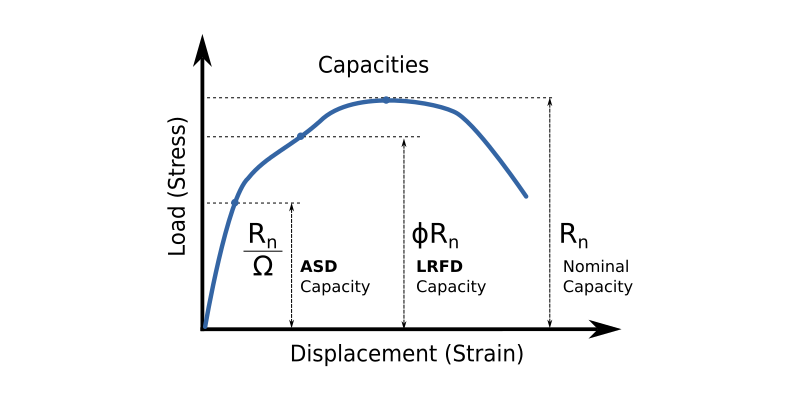
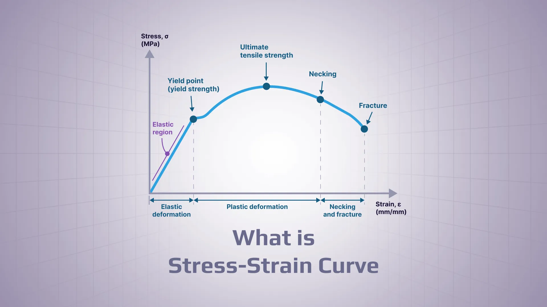
Comparison of LRFD/ASD Capacities On a Load vs. Displacement (Stress vs. Strain) Diagram
Both ASD and LRFD can be used with finite element analysis results, but they apply safety margins differently. In most FEA workflows, the difference is not in the mesh or solver. The difference appears in the load combinations, design factors, resistance checks, and final utilization criteria.
Note:In traditional engineering usage, ASD often means Allowable Stress Design. In modern AISC steel design terminology, ASD refers to Allowable Strength Design. The article uses both terms where relevant and explains the distinction above.
Checks service-level demand against allowable stress or strength limits
Checks factored demand against reduced design resistance
Simplified equation
\( R_u \leq \frac{R_n}{\Omega} \)
\( \sum \gamma_i Q_i \leq \phi R_n \)
Loads
Service-level or unfactored load combinations depending on code
Factored load combinations with partial load factors, depending on load type
Resistance / strength
Nominal resistance reduced by safety factor
Nominal resistance multiplied by a resistance factor ф, where ф<1.0 for most strength checks
Safety format
Safety embedded in allowable limits / factor of safety
Safety distributed between load and resistance factors
Factor notation
\( {\Omega} \) or factor of safety
\(\gamma\), \(\phi\)
FEA model
Same model, ASD-specific combinations and checks applied
Same model, LRFD-specific combinations and checks applied
FEA results usage
Compared to allowable stress or force limits
Compared to factored demand vs design resistance
Utilization result
Ratio of demand to allowable limit
Ratio of design stress/allowable stress
Common use
Older standards, working stress methods, offshore/crane/ older building/civil codes
Modern limit-state design in steel, infrastructure, civil, buildings, crane etc. codes
Main risk in comparison
Can appear conservative depending on load basis and code assumptions
Can appear more precise but is sensitive to correct factor definitions
Practical note
Simpler conceptually, but still requires correct code implementation in FEA
More formal reliability framework, but not inherently “better” in software
ASD vs LRFD Load Combinations in FEA
The difference between these two methods is that the LRFD method takes into account the individual influence of the specific load (i.e., probabilistic nature of the loads) and matches it to the strength of the material. Therefore, LRFD provides a more explicit reliability framework by separating load factors and resistance factors. However, it does not make the FEA model itself more accurate. Accuracy still depends on the model, boundary conditions, mesh, loads, material data, and correct post-processing.
In ASD, the load combinations, allowable limits, safety factors, and check formulas are defined by the selected standard. The same FEA model can be used, but the verification setup must match the ASD method. That is why the LRFD method is used in most new standards and revised older ones, mainly based on the conservative ASD method. LRFD is common in many modern standards for buildings, bridges, offshore structures, and lifting equipment. However, whether LRFD or ASD should be used depends on the governing standard and project specification. ad
Which Method Should Engineers Use: ASD or LRFD?
Engineers should not choose ASD or LRFD based on preference alone. The governing design standard, project specification, structure type, region, and client requirements define which method should be used.
In FEA, both methods can often use the same structural model. The difference appears in load combinations, design factors, resistance checks, and utilization criteria. LRFD is common in modern limit-state design frameworks, while ASD remains relevant where allowable-stress, allowable-strength, or working-stress formats are required.
Also, results for the same model but using different methods can slightly differ in outcome. For example, the utilization factor for a member calculated using LRFD can be just below the maximum limit, while when ASD is applied, it may be slightly exceeded depending on the case.
Common Mistakes When Comparing ASD and LRFD in FEA
When working with finite element analysis results, ASD and LRFD are often compared incorrectly due to differences in load definitions, safety formats, and design assumptions. Below are the most common mistakes engineers make when comparing the two methodologies:
Mixing ASD and LRFD load combinations in the same verification setup Using service-level (ASD) and factored (LRFD) load cases interchangeably leads to inconsistent utilization results and invalid comparisons.
Comparing results without checking the load basis Directly comparing stresses or forces without confirming whether they come from service loads (ASD) or factored loads (LRFD) is one of the most common errors.
Confusing allowable stress with design resistance ASD limits are based on allowable stress (or reduced allowable strength), while LRFD uses reduced resistance with factored loads. Treating them as equivalent leads to incorrect interpretations.
Ignoring factor definitions (Ω vs γ and φ) ASD typically uses a single safety factor (Ω or FS), while LRFD splits safety into load factors (γ) and resistance factors (φ). Mixing these approaches distorts the safety level.
Using the same utilization formula for both methods ASD and LRFD use fundamentally different check formats, so applying one utilization equation to both can produce misleading results.
Not aligning FEA post-processing with the governing code Even with a correct FE model, incorrect code setup in post-processing (checks, combinations, limits) invalidates the design verification.
Assuming the software automatically applies the correct method FEA tools do not “choose” ASD or LRFD correctly by default — the engineer must define load combinations, factors, and design checks explicitly.
Comparing utilization ratios directly between ASD and LRFD Utilization values are not directly comparable across methods because they are normalized differently.
Design Checks using LRFD and ASD Methodology in SDC Verifier
In SDC Verifier, ASD and LRFD checks are applied during the verification stage on top of FEA results. Engineers can define load sets and combinations, select the required standard, run code-based checks, review utilization factors, and generate calculation reports from the same workflow.
The table below lists some of the standards with corresponding methodology
Within SDC Verifier, engineers can verify FEA results against selected industry standards and document the checks in structured reports. The accuracy of the verification still depends on a correct FE model, load definition, boundary conditions, and standard setup. In addition, existing standards can be copied and customized when project-specific modifications are required. Using the formula editor, engineers can create standards from scratch following the ASD or LRFD philosophy.
The key difference between ASD and LRFD is how safety is introduced into the design check. ASD generally compares service-level demand with allowable strength or stress limits, while LRFD compares factored demand with reduced nominal resistance. In FEA-based verification, the correct method is defined by the standard and project requirements, not by the analysis software alone.
Apply ASD and LRFD checks directly in your FEA workflow
See how SDC Verifier helps engineers apply ASD, LRFD, WSD, and limit-state checks to FEA results using code-based load combinations, utilization checks, and automated reports.