Why Efficient Hydrodynamic Load Modeling is Essential for Sustainable Offshore Platforms
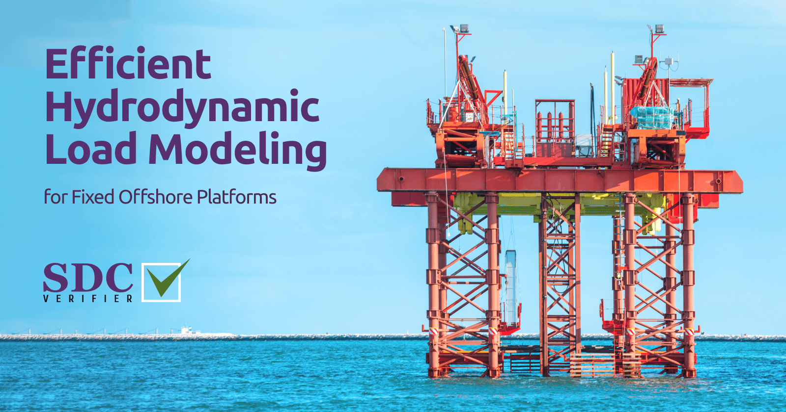
As climate change intensifies and sea levels rise, the resilience of offshore platforms is more critical than ever. Learn how advanced wave load modeling is helping engineers design structures that can withstand the growing challenges of our changing oceans.
Wave Load Modeling Fundamentals
The interaction of waves with offshore structures is a complex phenomenon, governed by fluid dynamics principles. At its core, wave loading arises from the fluctuating pressure field induced by wave motion. To model this behavior, engineers often employ wave theories, ranging from the simplified linear wave theory to more sophisticated higher-order theories that account for wave nonlinearities.
Wave loading on a PUQC platform’s steel jacket (Rong Doi oil field, Vietnam)
Wave Load Theory
Morison’s equation is a cornerstone of hydrodynamic load analysis for offshore structures. It provides a semi-empirical framework for estimating the force per unit length exerted by waves on slender cylindrical members, such as the legs of jacket platforms. The equation encapsulates two primary force components:
-
Drag Force (Fd): This force arises from the resistance of the water flow around the member. It is proportional to the square of the flow velocity and is characterized by the drag coefficient (Cd), which depends on the member’s shape, surface roughness, and Reynolds number.
-
Inertia Force (Fi): This force results from the acceleration of the water surrounding the member as the wave passes. It is proportional to the flow acceleration and is characterized by the inertia coefficient (Cm), which accounts for the added mass effect.
Morison’s equation combines these forces as follows:
F = Fd + Fi
Where:
- F is the total force per unit length
- Fd = (1/2) ρ Cd D u * |u| (drag force)
- Fi = ρ Cm (π/4) D^2 du/dt (inertia force)
- ρ is the fluid density
- D is the member diameter
- u is the flow velocity
- du/dt is the flow acceleration
Linear Wave Theory (Airy Wave Theory)
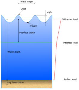
This fundamental theory provides a reasonable approximation for many offshore engineering applications. It assumes small-amplitude waves and sinusoidal wave profiles, making it computationally efficient. Key wave parameters in this context are wave height (H), wave period (T), and wavelength (L), which are interrelated.
Higher-Order Wave Theories
For steeper waves or situations where nonlinear effects become significant (e.g., shallow water), higher-order theories like Stokes’ wave theory or cnoidal wave theory offer improved accuracy. These theories consider wave asymmetry, peaked crests, and other nonlinear phenomena.
To go deeper into the challenges of verifying offshore structures, particularly floating wind plants, explore our article on the problems of verifying these structures according to industry standards.
Load Components: Inline and Transverse Forces
Wave-induced forces acting on offshore structures can be decomposed into two orthogonal components:
-
Inline Force (F_x): This force component acts parallel to the direction of wave propagation. It primarily arises from the drag force component of Morison’s equation and is responsible for pushing or pulling the structure in the direction of wave travel. Inline forces are typically the dominant force component for slender members like jacket legs.
-
Transverse Force (F_y): This force component acts perpendicular to the direction of wave propagation. It arises from both the drag and inertia force components of Morison’s equation and is responsible for inducing lateral vibrations and bending moments in the structure. Transverse forces are particularly significant for larger-diameter members or those with non-cylindrical shapes.
Understanding the interplay between inline and transverse forces is essential for assessing the overall loading pattern on a structure. For instance, the combination of inline and transverse forces can lead to complex vortex shedding phenomena, which can induce additional dynamic loads on the structure.
SDC Verifier Implementation
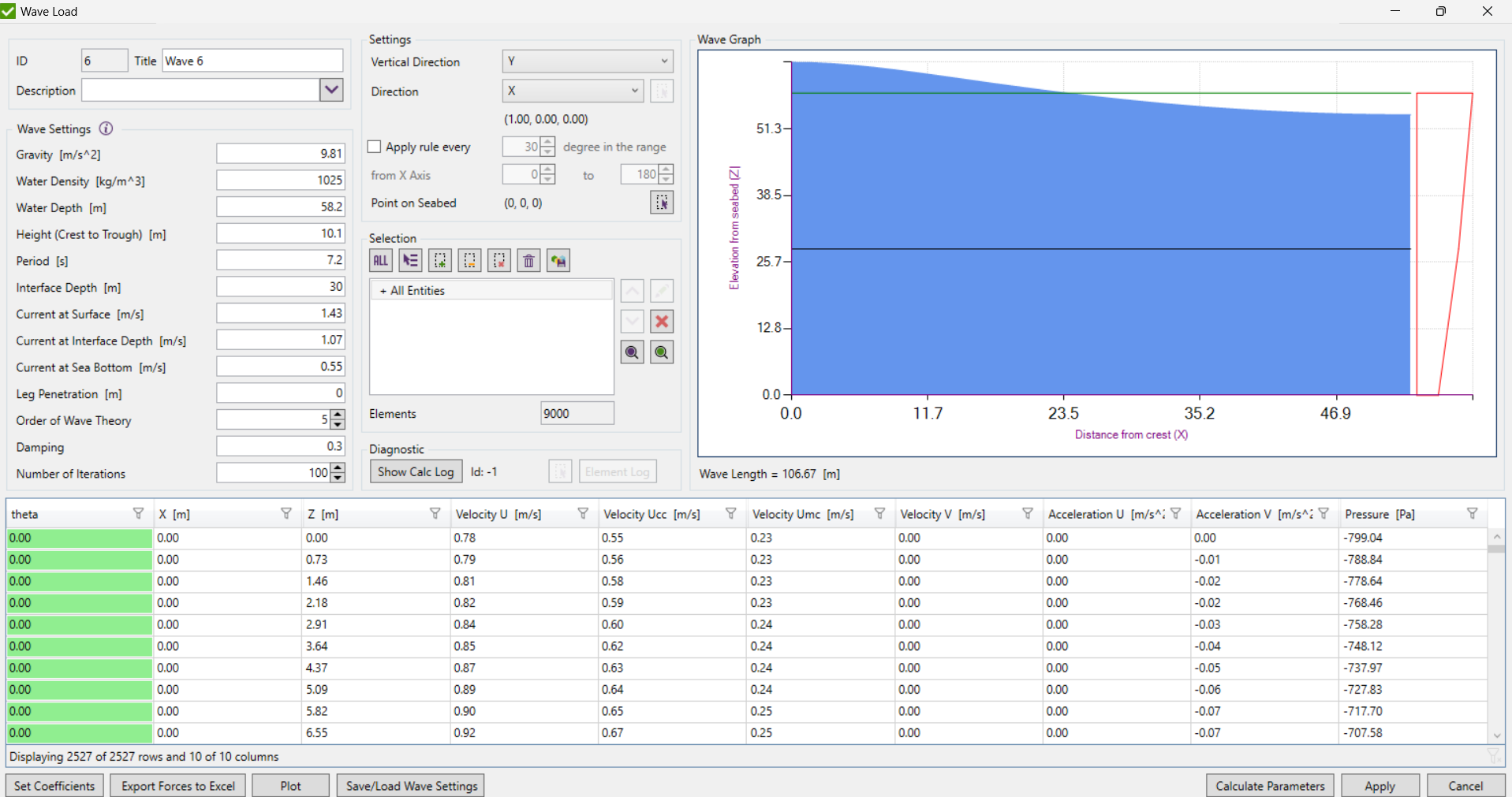
SDC Verifier simplifies the process of wave load modeling by providing a user-friendly interface and robust computational engine. Here’s a step-by-step guide on setting up a wave load case:
| Step | Description |
|---|---|
| Defining Water Properties | Specify seawater density for hydrostatic and hydrodynamic pressure calculations. |
| Wave Characteristics | Input wave height (H), wave period (T), and wave direction. Optionally provide wavelength (L) or let it be calculated. |
| Current Profile | Define current velocities at the surface, intermediate depth, and sea bottom. |
| Wave Load Calculation Options | Choose wave theory order, adjust damping parameters, and select the number of iterations. |
| Visualization | View the calculated wave profile and associated parameters like velocities, accelerations, and dynamic pressures. |
“Wave Graph” tab within the image showcases how SDC Verifier provides a visual representation of the calculated wave profile and its associated parameters.
Wave Coefficients
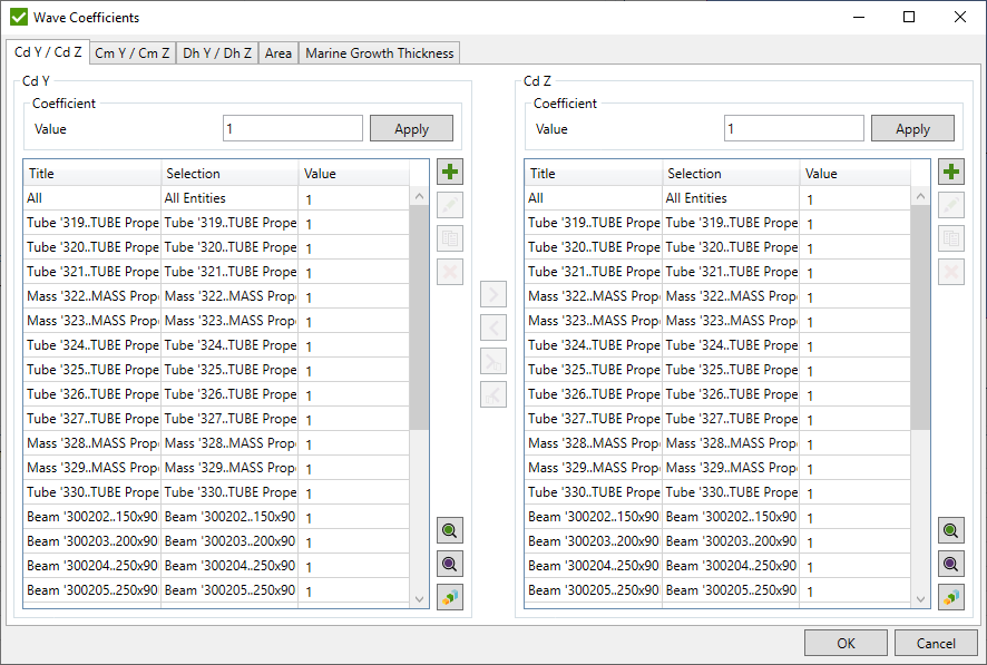
To translate wave kinematics into forces acting on the structure, SDC Verifier employs wave coefficients, namely:
- Drag Coefficient (Cd): This coefficient quantifies the resistance of a structural element to flow in the direction of wave propagation. It depends on the element’s shape, surface roughness, and Reynolds number.
- Inertia Coefficient (Cm): This coefficient accounts for the force required to accelerate the water surrounding the structural element. It is influenced by the element’s geometry and the added mass effect.
- Hydrodynamic Diameter (Dh): This parameter represents the effective diameter of the structural element for hydrodynamic load calculations. It is typically used in conjunction with Morison’s equation to estimate wave forces on slender members.
SDC Verifier allows users to define these coefficients for different element types based on empirical data, model tests, or industry guidelines.
Advanced Wave Load Modeling
Offshore environments are dynamic and subject to a wide spectrum of wave conditions. To ensure structural robustness, engineers must consider multiple wave scenarios that encompass varying sea states, storm events, and directional variability.
The importance of rigorous wave load analysis in developing safe and environmentally responsible solutions was highlighted during the decommissioning of the Brent Spar storage and tanker loading buoy, where alternative plans were needed after initial proposals faced intense scrutiny.
Multiple Wave Scenarios
SDC Verifier enables the creation and management of multiple wave load cases within a single project. This allows engineers to evaluate the structural response to different wave heights, periods, and directions, capturing the full range of potential loading conditions. For instance, a design might include:
- Operational Sea State: A representative wave condition for normal operation, characterized by moderate wave heights and periods.
- Extreme Sea State: A rare but critical event, such as a 100-year storm, with significantly larger wave heights and longer periods.
- Directional Variation: Multiple wave load cases with varying wave directions to assess the impact of oblique wave attack on the structure.
Customizing Wave Direction
SDC Verifier provides flexibility in defining wave direction. Users can specify the angle of wave approach relative to the global coordinate system, allowing for the simulation of waves coming from any direction.
This is particularly important for structures with asymmetrical geometries or those located in areas with complex wave patterns, and especially critical when modeling extreme events like hurricanes or rogue waves to ensure platform resilience.
Exporting Wave Load Data
To facilitate further analysis or verification, SDC Verifier enables the export of wave load data in various formats (e.g., CSV, Excel). This exported data can be used for:
- Post-Processing: Conducting detailed analysis of wave load distributions, calculating peak forces and moments, and generating customized reports.
- External Verification: Comparing SDC Verifier results with those obtained from other software tools or analytical methods to ensure accuracy and consistency.
- Design Optimization: Using the wave load data to refine the structural design, minimizing material usage while maintaining safety margins.
Marine Growth
Marine growth, the accumulation of biological organisms on submerged structures, is a persistent challenge in offshore engineering. While seemingly benign, marine growth can significantly alter the hydrodynamic properties of structural members, leading to increased drag and inertia forces, and consequently, higher structural loads.
Common Types of Marine Growth
Different types of marine organisms colonize offshore structures, each with unique growth patterns and effects:
- Hard Growth: Barnacles, mussels, and tubeworms form hard, calcareous shells that adhere tenaciously to surfaces. This type of growth significantly increases surface roughness and hydrodynamic diameter, leading to higher drag forces.
- Soft Growth: Algae, hydroids, and bryozoans form softer, more flexible colonies. While their impact on drag is less pronounced than hard growth, they can still contribute to increased loads, particularly in areas with high flow velocities.
Industry Guidelines for Accounting for Marine Growth
Recognizing the importance of marine growth considerations in offshore design, industry guidelines offer recommendations for mitigating its impact:
- DNVGL-RP-C205 : This recommended practice provides comprehensive guidance on the assessment of marine growth thickness, its effect on hydrodynamic loads, and strategies for incorporating it into the design process.
- API RP 2A-WSD: The American Petroleum Institute’s recommended practice also addresses marine growth, offering guidance on thickness estimation and its inclusion in load calculations.
These guidelines typically suggest applying a marine growth thickness allowance to the hydrodynamic diameter of structural members. The magnitude of this allowance depends on factors such as water depth, geographic location, and the expected operational life of the structure.
Validation and Verification
The adage “trust but verify” holds particular significance. Even with meticulous model preparation and load application, it’s imperative to rigorously validate and verify the results obtained from SDC Verifier. This ensures that the calculated wave loads are accurate, reliable, and compliant with industry standards.
Diagnostic Tools
SDC Verifier offers a suite of diagnostic tools that empower engineers to scrutinize their models and calculations. Two key tools are:
-
Calculation Log: This log file provides a detailed record of the wave load calculations performed by SDC Verifier. It includes information on wave parameters, coefficients, element forces, and convergence status. By examining this log, engineers can identify potential errors, such as incorrect input values, numerical instabilities, or convergence issues.
-
Element Log: This log focuses on the wave load calculations for individual elements. It details the forces and moments applied to each element, along with the associated wave parameters and coefficients. This information is invaluable for identifying localized load anomalies, verifying load distribution patterns, and troubleshooting element-specific issues.
Tips for Identifying and Resolving Errors
- Check Input Values: Ensure that all input parameters, such as water density, wave height, period, direction, and coefficients, are entered correctly and consistently with your project specifications.
- Visualize Results: Utilize SDC Verifier’s visualization capabilities to examine wave profiles, load distributions, and structural deformations. Look for any inconsistencies or unexpected patterns that may indicate errors in the model or load application.
- Conduct Sensitivity Analyses: Vary input parameters within a reasonable range and observe the impact on the results. This can help identify parameters that have a disproportionate influence on the calculated wave loads.
- Consult with Experts: If you encounter persistent issues or complex problems, don’t hesitate to seek guidance from experienced engineers or SDC Verifier support.
Comparison with Industry Standards
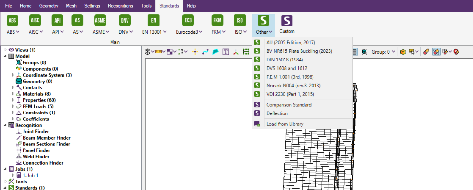
SDC Verifier simplifies the compliance process by seamlessly integrating industry-leading standards directly into your workflow. This eliminates the need for manual cross-referencing and ensures your designs adhere to the latest safety regulations and performance expectations.
Key standards integrated into SDC Verifier include:
- API RP 2A-WSD: Recommended Practice for Planning, Designing, and Constructing Fixed Offshore Platforms – Working Stress Design
- DNVGL-OS-C101: Design of Offshore Steel Structures, General (Det Norske Veritas)
- ISO 19902: Petroleum and natural gas industries – Fixed steel offshore structures
By comparing your results with these standards, you can assess the adequacy of your design, identify potential areas for improvement, and demonstrate compliance to regulatory authorities.
These findings have significant design implications, such as:
- Member Sizing. The dimensions of critical members may need to be adjusted to ensure they can withstand the maximum stresses without failure. Wave load modeling is routinely used to optimize member sizing in jacket platform design, leading to significant material savings and improved structural performance.
- Bracing Configuration. The arrangement of braces may be modified to enhance structural stiffness and reduce dynamic response.
- Foundation Design. The size and capacity of the foundation may need to be increased to resist the peak base shear and overturning moment.
- Fatigue Mitigation. Fatigue mitigation measures, such as weld profiling or the addition of stiffeners, may be implemented to extend the fatigue life of critical members.
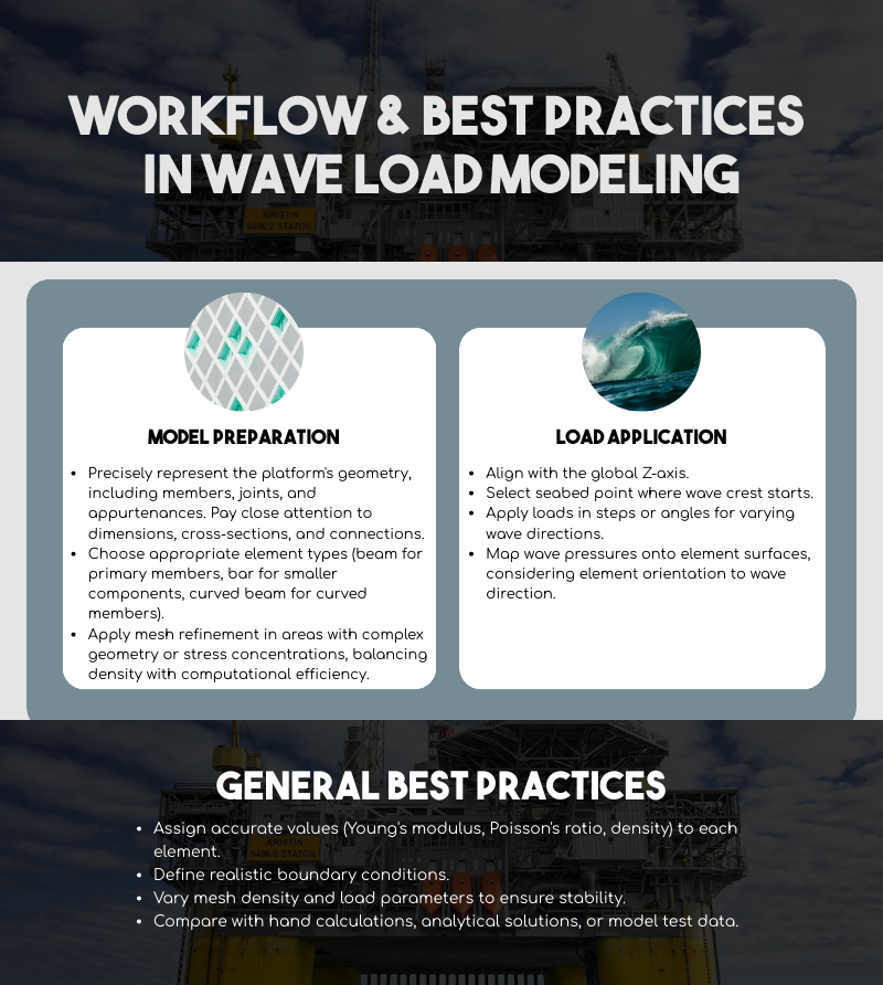
Engineering Workflow and Best Practices
The effectiveness of wave load modeling in SDC Verifier hinges on a well-prepared finite element model and meticulous load application. Adhering to best practices throughout this workflow ensures accurate results and informed design decisions.
By following these engineering workflow recommendations and adhering to best practices, you can maximize the accuracy and reliability of your wave load modeling efforts in SDC Verifier. This, in turn, will lead to safer, more efficient, and more cost-effective designs for fixed offshore platforms.
Conclusion
SDC Verifier’s capabilities extend beyond wave load modeling to include structural analysis, fatigue assessment, and dynamic response evaluation, providing a holistic view of platform performance. By rigorously validating and verifying results, SDC Verifier instills confidence in the accuracy and reliability of your engineering decisions.

