Example E.3 Built-Up column with slender flanges
The results are generated with SDC Verifier 3.6 and calculated with FEMAP v11.0.0
Task:
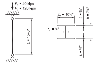
Determine if a built-up, ASTM A572 Grade 50 column with PL? in. × 10½ in flanges and a PL¼ in. × 7¼ in. The web has sufficient available strength to carry a dead load of 40 kips and a live load of 120 kips in axial compression. The column’s unbraced length is 15 ft in both axes and the ends are pinned.
Solution:
From AISC Manual Table 2-5, the material properties are as follows:
Built-Up Column
ASTM A572 Grade 50
- Fy = 50 ksi
- Fu = 65 ksi
The geometric properties are as follows:
Built-Up Column
- d = 8.00 in.
- bƒ = 10½ in.
- tƒ = ? in.
- h = 7¼ in.
- tw = ¼ in.
From Chapters 2 of ASCE/SEI, the required compressive strength is:
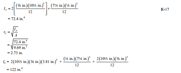
Built-Up Section Properties (ignoring fillet welds)
Ag = 2(10½ in.)(? in.) + 7¼ in.(¼ in.)
=9.69 in.2
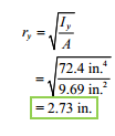
Because the unbraced length is the same for both axes, the weak axis will govern.
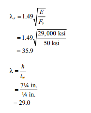
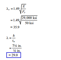
Weld Slenderness
Determine the limiting slenderness ratio, Λr, from AISC Specification Table B4.1 a case 5:
Λ < Λr; therefore, the web is not slender.
Note that the fillet welds are ignored in the calculation of h built up sections.
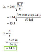
Flange Slenderness
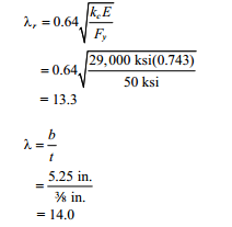
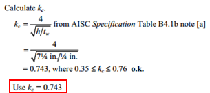
Calculate Kc–
Use kc = 0.743
Determine the limiting slenderness ratio, Λr, From AISC Specification Table B4.1a case 2.
Λ > Λr; therefore, the flanges are slender.
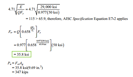
For compression members with slender elements, Section E7 of the AISC Specification applies. The nominal compressive strength, Pn, shall be determined based on the limit states of flexural, torsional and flexural-torsional buckling. Depending on the slenderness of the column, AISC Specification Equation E7-2 or E7-3 applies. Fee is used in both equation and is calculated as the lesser of AISC Specification Equation E3-4 or E4-4.
From AISC Specification Commentary Table C-A-7.1, for a pinned-pinned condition, K = 1.0.
Because the unbraced length is the same for both axes, the weak axis will govern.
Elastic Critical Stress, Fe, for Flexural Buckling
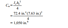
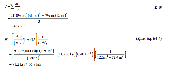
Elastic Critical Stress, Fe, for Torsional Buckling
Note: This limit state is not likely to govern, but the check is included here for completeness.
From the User Note in AISC Specification Section E4,
From AISC Design Guide 9, Equation 3.4,
Therefore, use Fe = 65.9 ksi.
Slenderness Reduction Factor Q
Q = QsQa from AISC Specification Section E7, where Qa = 1.0 because the web is not slender.
Calculate Qs, the unstiffened element (flange) reduction factor from AISC Specification Section E7.1(b).
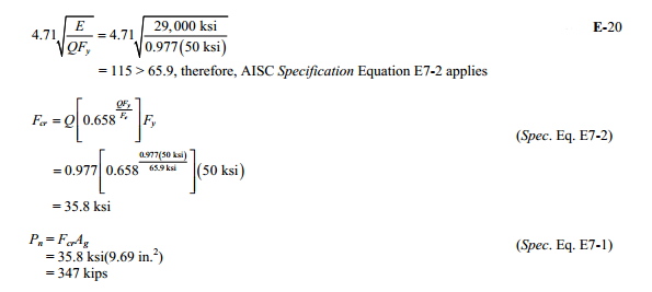
Determine the proper equation for Qs by checking limits for AISC Specification Equation E7-7 to E7-9.
Nominal Compressive Strength
From AISC Specification Section E1, the available compressive strength is:
Note: Built-up sections are generally more expensive than standard rolled shapes; therefore, a standard compact shape, such as a W8×35 might be a better choice even if the weight is somewhat higher. This selection could be taken directly from AISC Manual Table 4-1.
Example from AISC Design Examples
Material summary
Properties Summary
Area, moment Izz, moment Iyy and other shape parameters are corrected because in FEMAP it calculated without taken into account fillets and chamfers.
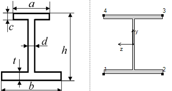
| Geometry Property | Value |
|---|---|
| Height | 8.00 |
| Width | 10.50 |
| h | 8.00 |
| a | 10.50 |
| b | 10.50 |
| c | 0.38 |
| d | 0.25 |
| t | 0.38 |
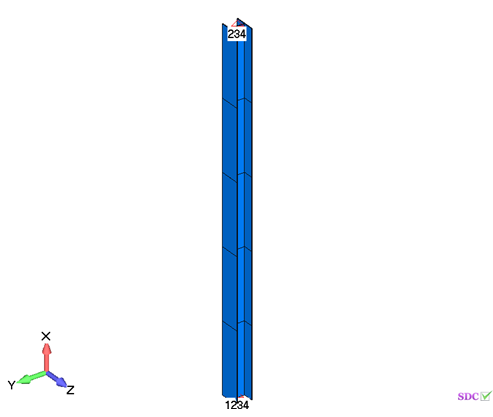
FEM Loads and Constraint
1..Dead load 40 kips
2..Live load 120 kips
Constraint
1..Pinned
Check 1..ANSI / AISC LRFD 360-10
Beam Characteristics
All (LS1, All Entities)
All (LS1, All Entities)
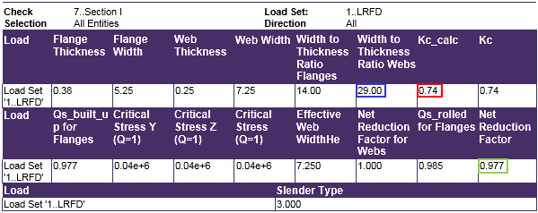
Web Slenderness
Determine the limiting slenderness ratioΛr, from AISC Specification Table B4.1a case 5:
Λ < Λ therefore, the web is not slender
Calculate kc–
Determine the limiting slenderness ratio,Λr, from AISC Specification Table B4.1a case 2:
Λ > Λ; therefore, the flanges are slender
Axial check
All (LS1, All Entities)
From AISC Specification Section E1, the available compressive strength is:
Comparing results of calculation in SDC Verifier and in Example E.2 we can see that values completely match. The available compressive strength is 312 kips.
