Example E.4A W-shape compression member (moment frame)
The results are generated with SDC Verifier 3.6 and calculated with FEMAP v11.0.0
This example is primarily intended to illustrate the use of the alignment chart for sideway uninhibited columns in conjunction with the effective length method.
Task:
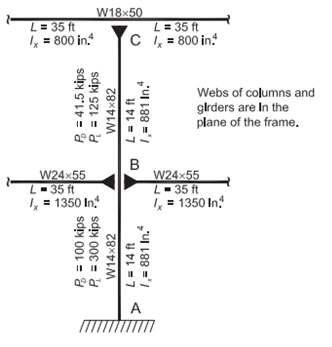
The member sizes are shown for the moment frame illustrated here (sideways uninhibited in the plane of the frame) have been determined to be adequate for lateral loads. The material for both the column and the girders is ASTM A992. The loads shown at each level are the accumulated dead loads and live loads at that story. The column is fixed at the base about the x-x axis of the column
Determine if the column is adequate to support the gravity loads shown. Assume the column is continuously supported in the transverse direction (the y-y axis of the column).
Solution:
From AISC Manual Table 2-4, the material properties are as follows:
ASTM A992
- Fy = 50 ksi
- Fu = 65 ksi
From AISC Manual Table 1-1, the geometric properties are as follows:
W18×50
- Ix = 800 in.4
- W24×55
- Ix = 1.350 in.4
W14×82
- Ag = 24.0 in.2
- Ix = 881 in.4
Column B-C
From Chapter 2 of ASCE/SEI 7, the required compressive strength of the column between the roof and floor is:
Effective Length Factor
Calculate the stiffness reduction parameter, τb using AISC Manual Table 4-21.
Therefore, no reduction in stiffness for inelastic buckling will be required.
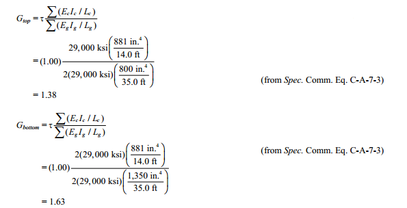
Determine Gtop and Gbottom.
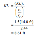
From the alignment chart, AISC Specification Commentary Figure C-A-7.2, K is slightly less than 1.5; therefore use K = 1.5. Because the column available strength tables are based on the KL about the y-y axis, the equivalent effective column length column length of the upper segment for use in the table is:
Take the available strength of the W14×82 from AISC Manual Table 4-1.
At KL = 9 ft, the available strength in axial compression is:
Column A-B
From Chapter 2 of ASCE/SEI 7, the required compressive strength of the column between the floor and foundation is:
Effective Length Factor
Calculate the stiffness reduction parameter, τb using AISC Manual Table 4-21.
Determine Gtop and Gbottom accounting for column inelasticity by replacing EcIc with τb(EcIc). Use τb = 0.994.
Gbottom = 1.0 (fixed) from AISC Specification Commentary Appendix 7, Section 7.2
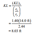
From the alignment chart, AISC Specification Commentary Figure C-A-7.2, i is approximately 1.40. Because the column available strength tables are based on the KL about the y-y axis, the effective column length of the lower segment for use in the table is:
Take the available strength of the W14×82 from AISC Manual Table 4-1.
At KL = 9 ft, (conservative) the available strength in axial compression is:
A more accurate strength could be determined by interpolation from AISC Manual Table 4-1.
Example from AISC Design Examples
Material summary
Properties Summary
1..W14×82
| Geometry Property | Value |
|---|---|
| Height | 14.30 |
| Width | 10.10 |
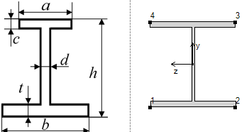
| h | 14.30 |
| a | 10.10 |
| b | 10.10 |
| c | 0.86 |
| d | 0.51 |
| t | 0.86 |
2..W24×55
| Geometry Property | Value |
|---|---|
| Height | 23.60 |
| Width | 7.01 |
| h | 23.60 |
| a | 7.01 |
| b | 7.01 |
| c | 0.51 |
| d | 0.40 |
| t | 0.51 |
2..W18×50
| Geometry Property | Value |
|---|---|
| Height | 18.00 |
| Width | 7.50 |
| h | 18.00 |
| a | 7.50 |
| b | 7.50 |
| c | 0.57 |
| d | 0.36 |
| t | 0.57 |
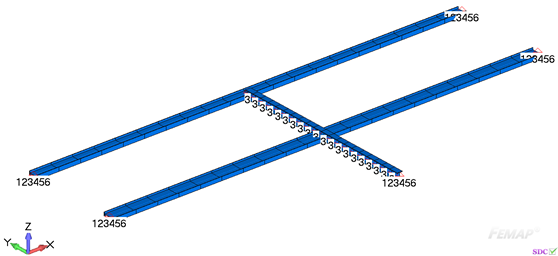
FEM Loads and Constraint
1..Dead load
2..Live load
Constraint
1.. Supports
Check 1..ANSI / AISC LRFD 360-10
Axial check
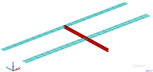
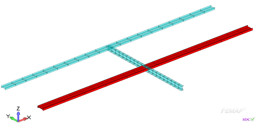
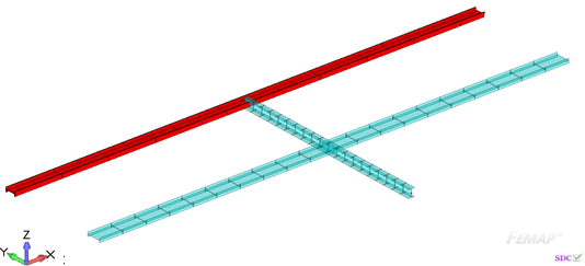
All (LS1, 2..BC)
All (LS1, 1..AB)
At KL = 9 ft, (conservative) the available strength in axial compression is:
Comparing results of calculation in SDC Verifier and in Example E.4A we can see that values completely match.
The available strength in axial compression is 951 kips.
Download SDC Verifier project file, model and report of Example E.4A
