Example F.3A W-shape flexural member with noncompact flanges in strong axis bending
The results are generated with SDC Verifier 3.7 and calculated with FEMAP v11
Task:
Select an ASTM A992 W-shape beam with a simple span of 40 ft. The nominal loads are a uniform dead load of 0.05 kip/ft and two equal 18 kip concentrated live loads acting at the third points of the beam. The beam is continuously braced. Also, calculate the deflection.
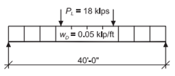
Beam Loading & Bracing Diagram (continuous bracing)
Note: A beam with noncompact flanges will be selected to demonstrate that the tabulated values of the AISC Manual account for flange compactness.
Solution:
From A Manual AISC Manual Table 2-4, the material properties are as follows:
- ASTM A992
- Fy = 50 ksi
- Fu = 65 ksi
From Chapter 2 of ASCE/SEI 7, the required flexural strength at midspan is:
Beam Selection
For a continuously braced W-shape, the available flexural strength equals the available plastic flexural strength. Select the lightest section providing the required strength from the bold entries in AISC Manual Table 3-2.
Try a W21×48
This beam has a noncompact compression flange at Fy = 50 ksi as indicated by footnote “f” in AISC Manual Table 3-2. This shape is also footnoted in AISC Manual Table 1-1.
From AISC Manual Table 3-2, the available flexural strength is:
Note: The value Mpx in AISC Manual Table 3-2 includes the strength reductions due to the noncompact nature of the shape.
Deflection
lx = 959 in.4 from AISC Manual Table 1-1
The maximum deflection occurs at the center of the beam.
from AISC Manual Table 3-23 cases 1 and 9
This deflection can be compared with the appropriate deflection limit for the application. Deflection will often be more critical than strength in beam design.
Example F.3B W-shape flexural member with noncompact flanges in strong axis bending
Task:
Verify the results from Example F.3A by calculation using the provisions of the AISC Specification.
Solution:
From AISC Manual Table 2-4, the material properties are as follows:
- ASTM A992
- Fy = 50 ksi
- Fu = 65 ksi
From AISC Manual Table 1-1, the geometric properties are as follows:
- W21×48
- Sx = 93.0 in.3
- Zx = 107 in.3
The required flexural strength from Example F.3A is:
Flange Slenderness
The limiting width-to-thickness ratios for the compression flange are:
from AISC Specification Table B4.1b Case 10
from AISC Specification Table B4.1b Case 10
λrf > λ > λpf, therefore, the compression flange is noncompact. This could also be determined from the footnote “f” in AISC Manual Table 1-1.
Nominal Flexural Strength, Mn
Because the beam is continuously braced, and therefore not subject to lateral-torsional buckling, the available strength is governed by AISC Specification Section F3.2, Compression Flange Local Buckling.
Mp = FyZx = 50 ksi(107 in.3 = 5.350 kip-in. or 446 kip-ft
from AISC Specification
From AISC Specification Section G1, the available shear strength is:
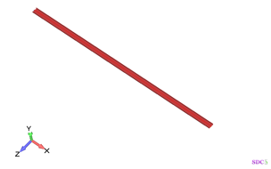
Example from AISC Design Examples
Material summary
Material summary
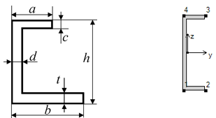
Properties Summary
| Geometry Property | Value |
|---|---|
| Height | 9.00 |
| Width | 2.65 |
| h | 9.00 |
| a | 2.65 |
| b | 2.65 |
| c | 0.41 |
| d | 0.45 |
| t | 0.41 |
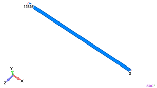
FEM Loads and Constraint
1..Dead load 10 kips
2..Live load 30 kips
Constraint
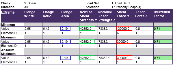
Check 1..ANSI / AISC LRFD 360-10
Shear
All (LS1, 17 Property Shape(s))
From Chapter 2 ASCE/SEI 7, the required shear strength is:
From AISC Specification Section G1, the available shear strength is
Comparing results of calculation in SDC Verifier and in Example G.7 we can see that values completely match.
The required shear strength is 30 kips.
The available shear strength is 42.55 kips.


