


Example F.7A HSS flexural member with noncompact flanges
The results are generated with SDC Verifier 3.7.1 and calculated with FEMAP v11.0.0. The Example was calculated in American unit system.
Task:
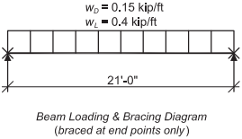
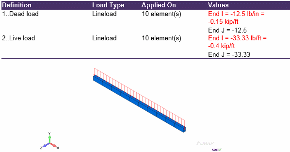
Select a rectangular ASTM A500 Grade B HSS beam with the span of 21 ft. The loads include a uniform dead load of 0.15 kip/ft and a uniform live load of 0.4 kip/ft. Limit the live load deflection to L/240. The beam is braced at the end points only. A noncompact member was selected here to illustrate the relative ease of selecting noncompact shaped from the AISC Manual, as compared to designing a similar shape by applying the AISC Specification requirements directly, as shown in Example F.7B.
Solution:
From AISC Manual Table 2-4, the material properties are as follows:
- ASTM A500 Grade B
- Fy = 46 ksi
- Fu = 58 ksi
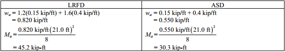
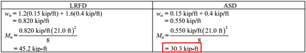
From Chapter 2 of ASCE/SEI 7, the required flexural strength is:
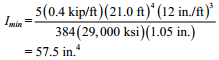
Minimum Required Moment of inertia
The maximum live load deflection permitted is:
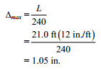
The maximum calculated deflection is:
![]()
Rearranging and substituting Δmax = 1.05 in.,
Beam Selection
Select rectangular HSS with a minimum lx of 57.5 in4.,using AISC Manual Table 1-11, and having adequate available strength, using AISC Manual Table 3-12.
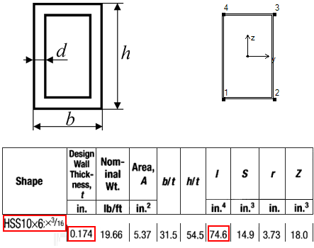
Try an HSS 10×6× 3/16 oriented in the strong direction. This rectangular HSS section was purposely selected for illustration purposes because it has a noncompact flange. See AISC Manual Table 1-12A for compactness criteria.
lx = 74.6 in4. > 57.5 in4. o.k.
For a quick check based on idealized rectangular HSS dimensions, use the calculator to calculate HSS section properties.
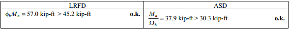
From AISC Manual Table 3-12, the available flexural strength is:
Example F.7B HSS flexural member with noncompact flanges
Task:
Notice that in Example F.7A the required information was easily determined by consulting the tables of the AISC Manual. The purpose of the following calculation is to demonstrate the use of the AISC Specification equations to calculate the flexural strength of an HSS member with a noncompact compression flange.
Solution:
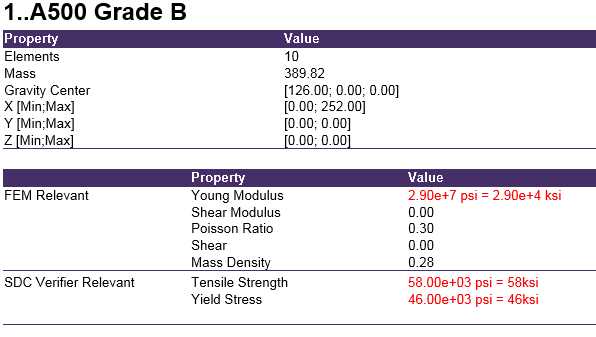
From AISC Manual Table 2-4, the material properties are as follows:
- ASTM A500 Grade B
- Fy = 46 ksi
- Fu = 58 ksi
From AISC Manual Table 1-11, the geometric properties are as follows:
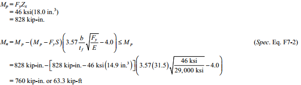
- HSS 10×6× 3/16
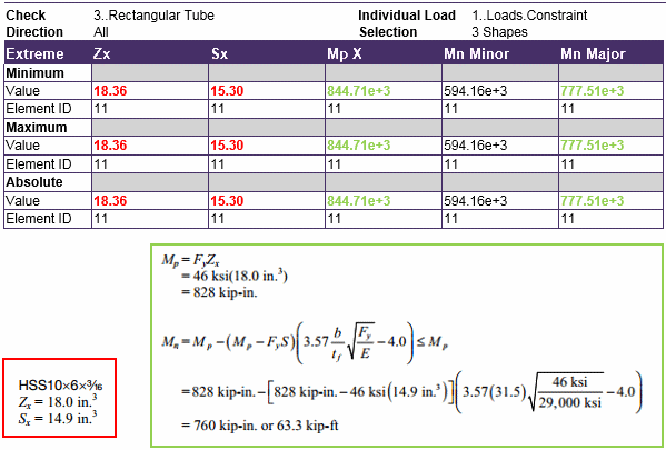
- Zx = 18.0 in.3
- Sx = 14.9 in.3
Flange Compactness
![]()
= 31.5 from AISC Manual Table 1-11
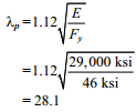
Determine the limiting ratio for a compact HSS flange in flexure from AISC Specification Table B4.1b Case 17.
Flange Slenderness
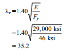
Determine the limiting ratio for a slender HSS flange in flexure from AISC Specification Table B4.1b Case 17.
flexure from AISC Specification Table B4.1b Case 17.
Λp<Λ<Λr therefore the flange is noncompact. For this situation, AISC Specification Equation F7-2 applies
Web Slenderness
![]()
= 54.5 from AISC Manual Table 1-11
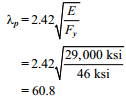
Determine the limiting ratio for a compact HSS web in flexure from AISC Specification Table B4.1b Case 19.
Λ < Λp therefore, the web is compact
For HSS with noncompact flanges and compact webs, AISC Specification Section F7.2(b) applies.
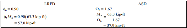
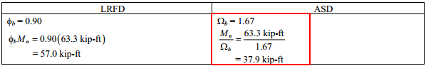
From AISC Specification Section F1, the available flexural strength is:
Units which were used in calculation:
- 1 kip = 1000lb
- 1 ft = 12 in
- 1 ksi = 1000 psi (lb/in^2)
Example from AISC Design Examples
Material summary
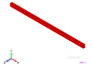
Properties Summary
![]()
| Geometry Property | Value |
|---|---|
| Height | 10.00 |
| Width | 6.00 |
| h | 10.00 |
| b | 6.00 |
| D | 0.174 |
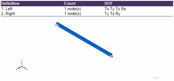
FEM Loads and Constraint
1..Loads
Constraint
Individual Load ‘1..Loads.Constraint’
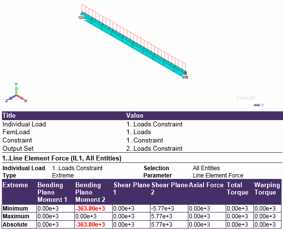
From Chapter 2 of ASCE/SEI 7, the required flexural strength is
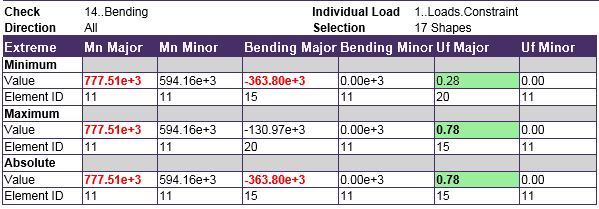
Convert values: 363.80e+03 lb-in = 30.31 kip-ft
Check 1..ANSI / AISC LRFD 360-10
1..HSS (square and rectangular)
2..Bending
From AISC Specification Section F1, the available flexural strength is:
Utilization factor
- 777.51 kip-in = 64.79 kip-ft;
- 363.8 kip-in = 30.31 kip-ft;
- 64.79 kip-ft/1.67 =38.79 kip-ft
- 30.31/38.79 = 0.78
Comparing results of calculation with SDC Verifier and Example F.7 can be seen that values coincide. Slight difference is explained by converting units from one to another and using conservative shape of the beam in Femap.
The required flexural strength is 30.31 kip-ft.
The available flexural strength is 38.79 kip-ft.
Download SDC Verifier project file, model and report of Example F.7


