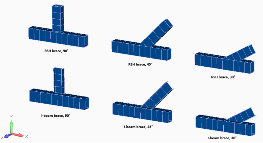
Example – Determine the utilization for the 6 presented configurations of joints with I-beam/RHS braces and RHS chords according to Eurocode 3 EN 1993-1-8 (2005)
This benchmark was prepared based on
external documents
using
SDC for Femap and Simcenter Femap Version 2022.2
This benchmark demonstrates how to determine the utilization factors of joints with RHS chords and I-beam/RHS braces using SDC Verifier according to Eurocode 3 EN 1993-1-8 (2005). For this analysis, six specific joint configurations have been considered. Detailed material, geometric properties and weld specifications are provided. Loads and constraints applied to the model are outlined, and the rationale for weld configuration choices is described.
Analysis Overview
The analysis focuses on a common structural detail: an I-beam or RHS brace connecting to a main structural member (chord) at a defined angle, typically 45 degrees. The calculations involve:
- Material and geometric properties: including yield strength, cross-sectional dimensions, and joint angle.
- Weld parameters: types, sizes, and calculation methods.
- Applied loads and constraints: boundary conditions simulating real-world loading.
- Stress analysis: determination of stresses in the welds and brace members.
- Utilization factors: calculated to assess whether welds and brace members can withstand the applied loads.
Software Tools
- SDC Verifier: A structural analysis software specifically designed for the verification of steel connections and joints according to industry standards, including Eurocode 3.
Materials and Properties
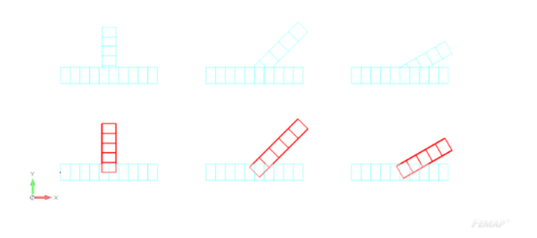
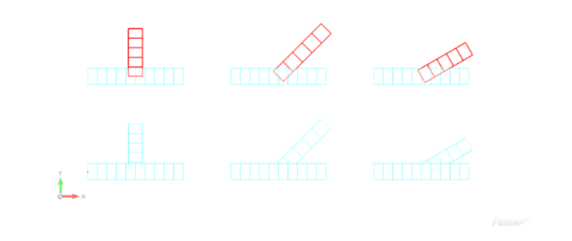
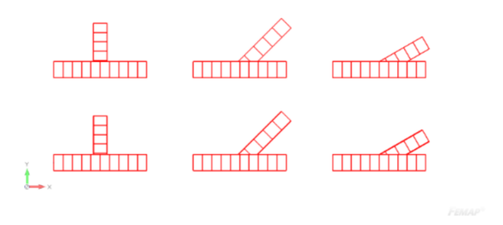
For the purpose of this benchmark the following 6 configurations of joints have been chosen:
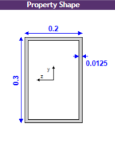
Detailed information about the material and section geometry can be seen below as presented in SDC Verifier:
Mild Steel
| Property | Value |
| Elements | 90 |
| Mass [kg] | 1832.16 |
| Gravity Center (CSys: 0) [m] | [4.13; 1.21; 0.00] |
| Young Modulus [Pa] | 200000000000 |
| Shear Modulus [Pa] | 80000000000 |
| Poisson Ratio | 0.3 |
| Shear [Pa] | 0 |
| Mass Density [kg/m^3] | 7850 |
| Tensile Strenght [Pa] | 470000000.00 |
| Yield Stress [Pa] | 355000000.00 |
Validate your steel structure designs with confidence. Our AS 4100 benchmarks, derived from official examples and verified with SDC Verifier, cover beam design, column design, and combined loading scenarios.
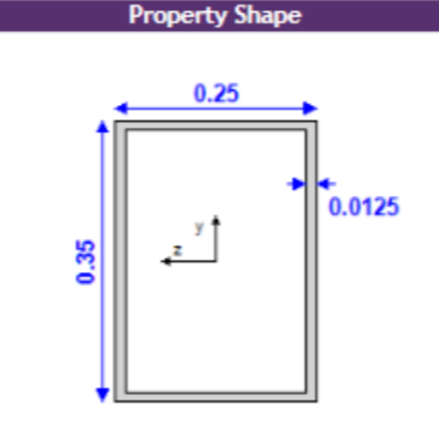
RHS 350x250x12.5
| Property | Value |
| Type | Beam / 60 |
| Material | Mild Steel |
| Mass [kg] | 1354.13 |
| Gravity Center [m] | [4.00; 1.00; 0.00] |
| Area, [m²] | 0.01 |
| 11, [m⁴] | 2.496E-04 |
| 12, [m⁴] | 1.472E-04 |
| 112, [m⁴] | 0 |
| Torsion Constant, [m⁴] | 2.858E-04 |
| Y Shear Area, [m²] | 0.01 |
| Z Shear Area, [m²] | 4.930E-03 |
| Nonstructural Mass, [kg] | 0 |
| Perimeter, [m] | 1.2 |
| Warping Constant, [m⁶] | 0 |
| Y Neutral Axis Offset A, [m] | 0 |
| Z Neutral Axis Offset A, [m] | 0 |
| h [m] | 0.35 |
| w [m] | 0.25 |
| t [m] | 0.01 |
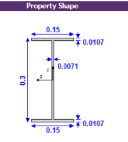
IPE 300
| Property | Value |
| Type | Beam / 15 |
| Material | Mild Steel |
| Mass [kg] | 145.35 |
| Gravity Center [m] | [4.49; 0.43; 0.00] |
| Area, [m²] | 0.01 |
| 11, [m⁴] | 7,999E-05 |
| 12, [m⁴] | 6.027E-06 |
| 112, [m⁴] | 0 |
| Torsion Constant, [m⁴] | 1.569E-07 |
| Y Shear Area, [m²] | 2.020E-03 |
| Z Shear Area, [m²] | 3.166E-03 |
| Nonstructural Mass, [kg] | 0 |
| Perimeter, [m] | 1.19 |
| Warping Constant, [m⁶] | 0 |
| Y Neutral Axis Offset A, [m] | 0 |
| Z Neutral Axis Offset A, [m] | 0 |
| h [m] | 0.3 |
| wt [m] | 0.15 |
| wb [m] | 0.15 |
| tf2 [m] | 0.01 |
| tw [m] | 0.01 |
| tf1 [m] | 0.01 |
RHS 300x200x12.5
| Property | Value |
| Type | Beam / 60 |
| Material | Mild Steel |
| Mass [kg] | 332.69 |
| Gravity Center [m] | [4.49; 2.43; 0.00] |
| Area, [m²] | 0.01 |
| 11, [m⁴] | 1.467E-04 |
| 12, [m⁴] | 7.718E-05 |
| 112, [m⁴] | 0 |
| Torsion Constant, [m⁴] | 1.572E-04 |
| Y Shear Area, [m²] | 0.01 |
| Z Shear Area, [m²] | 3.864E-03 |
| Nonstructural Mass, [kg] | 0 |
| Perimeter, [m] | 1 |
| Warping Constant, [m⁶] | 0 |
| Y Neutral Axis Offset A, [m] | 0 |
| Z Neutral Axis Offset A, [m] | 0 |
| h [m] | 0.3 |
| w [m] | 0.2 |
| t [m] | 0.01 |
The analysis focuses on a joint where an I-beam brace connects to a chord (main structural member) at a 45-degree angle.
Key Dimensions and Properties
-
Chord Section
- In-plane height: 350 mm
- Out-of-plane widht: 250 mm
- Thickness (flange and web): 12.5 mm
-
Brace Section
- In-plane height: 424.26 mm
- Out-of-plane widht: 150 mm
- Flange thickness: 10.7 mm
- Web thickness: 7.1 mm
Material Properties
- The chord and brace have identical yield strengths of 355 MPa.
- The allowable weld stress is based on EN 1993-1-8 and has an ultimate strength of 470 MPa, while SDC Verifier takes the minimum tensile strenght of all the connected parts.
Loads and Constraints
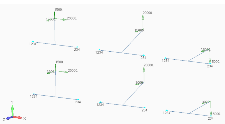
Loads and constraints have been defined as follows:
Loads
| Definition | Load Type | Applied On | Values |
| I-beam Z 3 kN | Force | Points: 6, 12, 18 | (0; 0; 3000) |
| RHS Z 15 kN | Force | Points: 24, 30, 36 | (0; 0; 15000) |
| 90deg X 20 kN | Force | Points: 6, 24 | (20000; 0; 0) |
| 45deg Y 20 kN | Force | Points: 12, 30 | (0; 20000; 0) |
| 30deg Y -15 kN | Force | Points: 18, 36 | (0; -15000; 0) |
| 90deg Y 1.5 kNm | Moment | Points: 6, 24 | (0; 1500; 0) |
Constraints
| Definition | Count | DOF |
| Left, Pinned | Points: 1, 7, 13, 19, 25, 3 | Tx Ty Tz Rx |
| Right, Pinned with T | Points: 4, 10, 16, 22, 28, 34 | Ty Tz Rx |
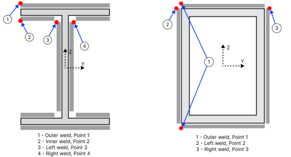
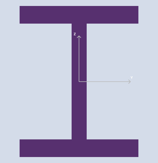
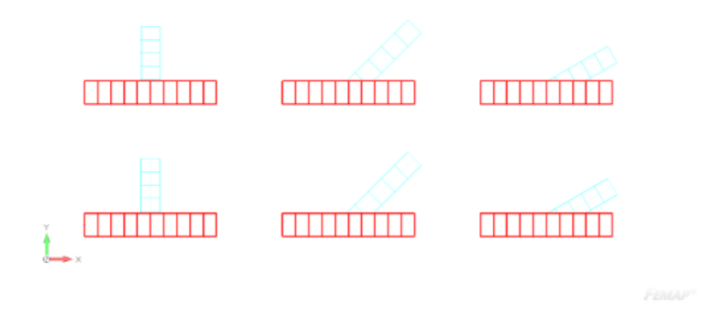
The stress levels and utilization factors of the brace welds are checked in four most critical locations for I-beam braces and in three for RHS braces according to the graph below:
Weld Types and Sizes
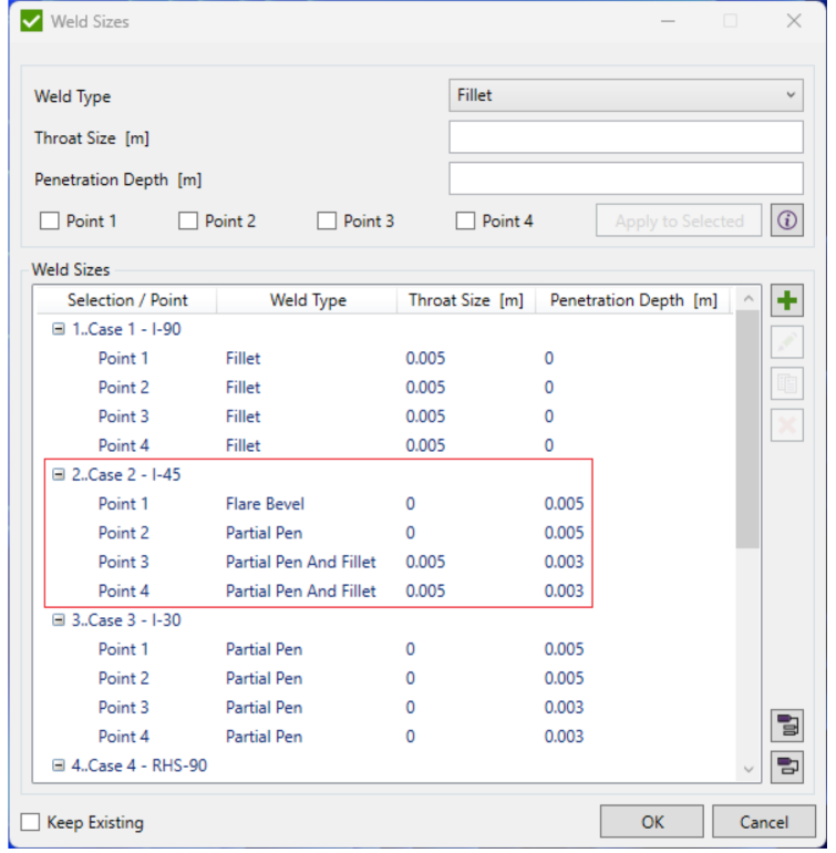
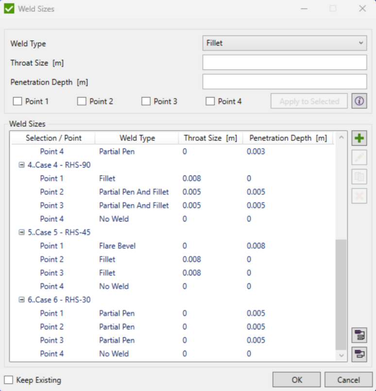
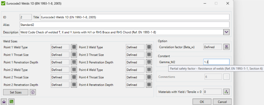
The definitions of these points are used to define the weld types and sizes of the designed joint, these can be done in an additional window when adding the standard to the project. The following types and sizes have been chosen:
Weld Configuration
- Flange Welds:
- Outer side: Flare bevel weld
- Inner side: Partial penetration weld
- Web Welds
- Both left and right sides: Partial penetration weld combined with a fillet weld.
Weld Dimensions (mm)
- Flanges
- Outer weld size: 5 mm
- Inner weld size: 5 mm
- Web
- Left weld size: Throat Size – 5 mm, Penetration Depth – 3 mm
- Right weld size: Throat Size – 5 mm, Penetration Depth – 3 mm
Throat Thickness for Combined Welds (mm)
- Automatic calculation is used for determining the effective throat thickness of partial penetration plus fillet weld combinations.
Gain in-depth understanding of AISC 360-10 through benchmarks based on official design examples. Explore tension, compression, flexure, and more! Models provided for Ansys, Femap, and Simcenter.
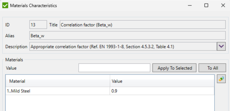
Two additional parameters have to be defined when adding the standard – the Correlation Factor ?? and the partial safety factor ym2:
In this case the value of ??2 has been defined as 1.3 according to Norsok N-004. In the case of Eurocode 3 EN 1993-1-1 the suggested value is 1.25 (which is also the default value when adding the standard).
Weld Stress Considerations
- Ultimate Strength: The weld material has an ultimate strength of 470 MPa (based on EN 1993-1-8).
- Correction Factor: A weld correction factor of 0.9 is applied.
- Material Factor: A weld material factor of 1.3 is used (in line with Norsok N-004 guidelines).
The loads at the brace weld cross-section that result from the applied boundary conditions can be checked in Check ID3 “Forces and Moments”:
| Standard | 2.. Eurocode3 Welds 1D (EN 1993-1-8, 2005) | Check | [S2] |
| Load Set | LS1..Loads | Selection | All Entities |
| Title | Axial Force X [N] | QP Shear Force [N] | IP Shear Force [N] | Force Torque [Nm] | IPB Moment [Nm] | OPB Moment [Nm] |
| Case 4 RHS-90 | 0 | 15000 | -20000 | 1500 | -20000 | 15000 |
| Case 5 RHS-45 | 14142.14 | 15000.01 | 14142.14 | 0 | 20000.01 | 21213.22 |
| Case 6 | -7500 | 15000.02 | -12990.4 | 0 | -15000.02 | 17320.52 |
| Case 11-90 RHS-30 | 0 | 3000 | -20000 | 1500 | -20000 | 3000 |
| Case 2-1-45 | 14142.14 | 3000.00 | 14142.14 | 0.00 | 20000.01 | 4242.64 |
| Case 31-30 | -7500 | 3000 | -12990.4 | 0 | -15000.02 | 3464.1 |
| AbsMax over Connections | 14142.14 | 15000.02 | -20000 | 1500 | 20000.01 | 21213.22 |
Loads on the Brace Weld Cross-Section
The brace weld experiences various forces and moments. Here’s a breakdown, keeping in mind that the coordinate system defines “z” as up and “y” as to the side:
Forces:
- Force in the x-axis (F_x): 14142.14 N
- Force in the y-axis (F_y): 3000 N
- Force in the z-axis (F_z): 14142.14 N
Moments:
- Bending moment about the y-axis (M_y): 20000 N-m
- Bending moment about the z-axis (M_z): 4242.64 N-m
- Torsional moment about the x-axis (M_x): 0 N-m (doesn’t exist in this case)
Results
The normal and equivalent stress capacities, as well as normal and equivalent maximum weld stresses for both brace flange and brace web welds can be checked in Check ID8 “Weld Stresses”:
|
Standard |
2.. Eurocode3 Welds 1D (EN 1993-1-8, 2005) |
Check |
[S2] |
|
Load Set |
LS1..Loads |
Selection |
All Entities |
|
Title |
Weld Ultimate Tensile Strength [Pa] |
Weld Normal Stress Capacity [Pa] |
Weld Equivalent Stress Capacity [Pa] |
Max sigma_1 Brace Welds [Pa] |
Max sigma_EQ Brace Welds [Pa] |
Max sigma_1 Brace Web [Pa] |
Max sigma_EQ Brace Web [Pa] |
|
Case 4 RHS-90 |
4.70E+08 |
325.4E+08 |
401.7E+6 |
15.3E+6 |
32.3E+6 |
15.3E+6 |
30.9E+6 |
|
Case 5 RHS-45 |
4.70E+08 |
325.4E+08 |
401.7E+6 |
88.4E+6 |
88.4E+6 |
62.3E+6 |
124.6E+6 |
|
Case 6 RHS-30 |
4.70E+08 |
325.4E+08 |
401.7E+6 |
49.5E+6 |
51.2E+6 |
49.5E+6 |
49.7E+6 |
|
Case 1 I-90 |
4.70E+08 |
325.4E+08 |
401.7E+6 |
-2.9E+06 |
129.7E+6 |
-25.3E+6 |
125.5E+6 |
|
Case 2 I-45 |
4.70E+08 |
325.4E+08 |
401.7E+6 |
83.2E+6 |
83.2E+6 |
21.8E+6 |
43.7+6 |
|
Case 3 I-30 |
4.70E+08 |
325.4E+08 |
401.7E+6 |
30.1E+6 |
30.2E+6 |
-13.3E+6 |
15.1E+6 |
|
AbsMax over Connections |
4.70E+08 |
325.4E+08 |
401.7E+6 |
88.0E+6 |
129.7E+6 |
62.3E+6 |
125.5E+6 |
Weld Stress Analysis Results
- Brace Flange:
- Maximum normal stress is 83.2 MPa.
- Maximum equivalent stress has the same value, 83.2 MPa.
- Brace Web
- Maximum normal stress is at 21.8 MPa.
- Maximum equivalent stress is calculated at 43.7 MPa.
If to look for potential causes of stress overshoots the individual stress components for all points can be checked in Checks ID4 to ID7.
Finally, the utilization factors can be checked in check ID9:
|
Standard |
2.. Eurocode3 Welds 1D (EN 1993-1-8, 2005) |
Check |
[S2] |
|
Load Set |
LS1..Loads |
Selection |
All Entities |
|
Title |
UF_N Brace Flange |
UF_EQ Brace Flange |
UF_N Brace Web |
UF_EQ Brace Web |
UF_IBeam |
UF_RHS |
UF Overall |
|
Case 4 RHS-90 |
0.05 |
0.08 |
0.05 |
0.08 |
0 |
0.08 |
0.08 |
|
Case 5 RHS-45 |
0.27 |
0.22 |
0.19 |
0.31 |
0 |
0.31 |
0.31 |
|
Case 6 RHS-30 |
0.15 |
0.13 |
0.15 |
0.12 |
0 |
0.15 |
0.15 |
|
Case 1 1-90 |
0.01 |
0.32 |
0.08 |
0.31 |
0.32 |
0 |
0.32 |
|
Case 2 1-45 |
0.26 |
0.21 |
0.07 |
0.11 |
0.26 |
0 |
0.26 |
|
Case 3 1-30 |
0.09 |
0.08 |
0.04 |
0.04 |
0.09 |
0 |
0.09 |
|
AbsMax over Connections |
0.27 |
0.32 |
0.19 |
0.31 |
0.32 |
0.31 |
0.32 |
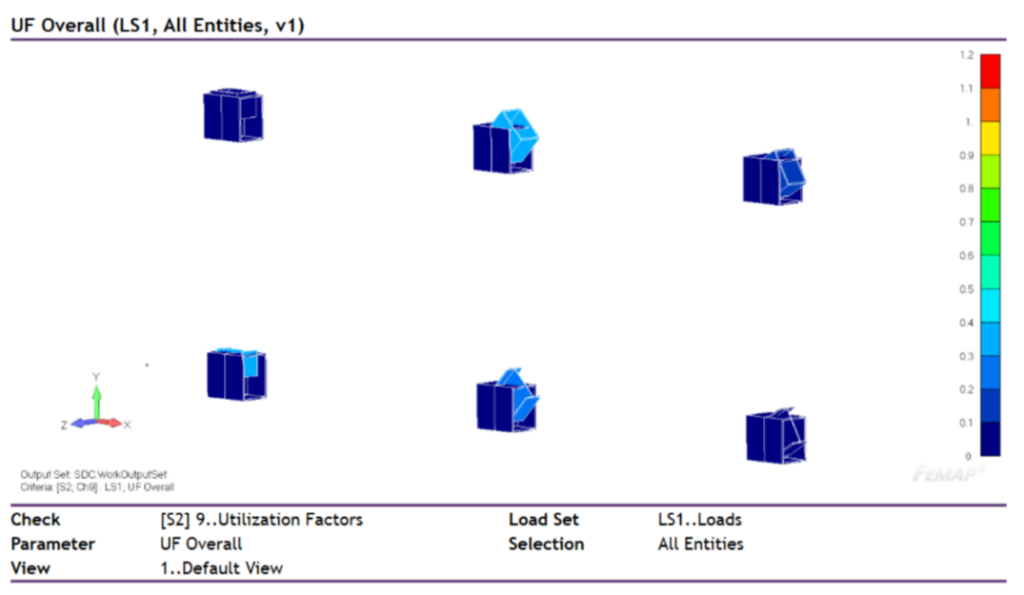
Values highlighted are passing the check (Uf < 1). The results can also be plotted on the model.
Weld Utilization Summary
- Brace Flange:
- Maximum normal stress utilization: 0.26
- Maximum equivalent stress utilization: 0.21
- Brace Web:
- Maximum normal stress utilization: 0.07
- Maximum equivalent stress utilization: 0.11
Key Observation: Weld utilization values are within acceptable limits, as indicated by “OK=1” for both sections.
As we can see the results agree completely with the external documents, they do so as well for the 5 other cases not presented in this document, but can be shown on demand.
Conclusion
The benchmark successfully demonstrates the calculation of joint utilization factors using SDC Verifier. The results, including weld stress levels, utilization factors, and individual stress components, are provided. The analysis indicates that the chosen weld configurations for the six presented joint cases satisfy the strength requirements with acceptable safety margins, as the utilization factors (Uf) are below 1. According to Eurocode 3 EN 1993-1-8 (2005), the analysis methodology and design criteria employed in this benchmark are in compliance with the relevant standards for steel joint connections.
