From CAD to FEA: How Geometry Bridges the Design-Analysis Gap
The transition from Computer-Aided Design (CAD) to Finite Element Analysis (FEA) is a crucial step in engineering, where design models are tested for real-world performance. Geometry is key in linking the design phase with the analysis stage. However, this transition involves several detailed steps, each essential for accurate simulations.
This article will explore the geometry preparation process and the workflow that connects CAD to FEA, highlighting the key methods and best practices.
Understanding the Transition from CAD to FEA
1. Geometry Export
The first step in the transition process is exporting the CAD model into a file format that FEA software can read and interpret.
Common Export Formats:
- STEP (.stp): STEP files are widely used to exchange 3D model data between CAD and FEA systems. They transfer the final geometry, such as feature history or parametric relationships. Despite these limitations, STEP is a neutral format compatible with most CAD software, making it an ideal choice for Model-Based Definition (MBD) workflows and cross-platform collaboration.
- IGES (.igs): IGES is another standard format suitable for surface models. It is compatible with many CAD and FEA tools and can handle wireframe and surface geometries.
- STL (.stl): STL files are widely used in 3D printing and FEA workflows to transferring surface geometry. They represent models as triangulated surfaces and lack design intelligence, such as feature history or parametric relationships.
2. Geometry Simplification
Once the model is exported, the geometry is often too complex for direct analysis in FEA software. The simplified geometry preparation makes the model more computationally feasible while retaining essential features that affect structural performance.
De-featuring:
Non-essential details like fillets, blends, small holes, sharp edges, features, engravings, and any non-structural features that create problems with mesh generation but do not influence the results are removed. These elements do not significantly influence the analysis but can complicate mesh generation, forcing the creation of a very fine mesh. This, in turn, increases computational load and significantly slows down the solver.
- In some cases, many non-structural components that do not contribute to the structural performance (e.g., holes in an inner section of a part often are not subjected to high stress) are removed to optimize the model.
Geometry Abstraction:
- Complex Geometries to Simple Approximations: Features like threads, small ridges, or internal ribs are often replaced with simpler forms. For example, a smooth cylinder might replace complex thread geometry for stress testing, as the threaded area’s contribution to overall structural integrity may not be critical in an FEA context.
- Simplifying Assemblies: Not all parts in large assemblies need to be included in the FEA model. Irrelevant components or sub-assemblies that do not affect the overall analysis are suppressed or simplified to reduce computational demands.
Feature Replacement:
- Small features that might complicate meshing can be replaced with simplified shapes. For instance, small bolt holes can be omitted if the precise geometry isn’t critical to the analysis’s outcome.
2. Material Assignment
Now, material properties are assigned to the mesh. Accurate material data is essential for ensuring that the analysis reflects the actual behavior of the material under load.
Types of Material Properties:
- Elastic Properties: Include Young’s Modulus, Poisson’s Ratio, and Shear Modulus (G). Young’s Modulus describes the material’s stiffness, Poisson’s Ratio indicates its ability to deform elastically, and Shear Modulus measures the material’s response to shear stress. Often, Shear Modulus is automatically calculated based on Young’s Modulus and Poisson’s Ratio.
- Plastic Properties: Yield strength, ultimate tensile strength, and strain hardening parameters, which define the elastic behavior, plastic, elasto-plastic, etc.
- Thermal Properties: In thermal analysis, material-specific properties such as thermal conductivity, specific heat, and coefficient of thermal expansion are applied.
Material Variability:
- Materials may have different properties in different regions of the model. For example, one part of the model is made of steel while another is made of aluminum.
3. Meshing
Meshing is the critical step in the FEA process. It divides the geometry into smaller more minor, discrete elements that can be analyzed individually. The quality of the mesh directly impacts the accuracy and performance of the analysis.
Types of Elements:
- 1D Elements (Beams): Often used by engineers for structures like beams and trusses. They are efficient for modeling long, slender components where bending and axial loads are significant.
- 2D Elements (Shells): Used for thin-walled structures such as plates and beams. Shell elements allow for efficient analysis of surfaces without excessive computational resources.
- 3D Elements:
- Tetrahedral Elements: Commonly used for complex geometries that do not conform easily to regular shapes. They are good for capturing irregular geometries but require more computational resources.
- Hexahedral Elements: Often used for more structured geometries like cubes or blocks. They provide higher accuracy and are computationally more efficient.
Mesh Refinement:
- Global Mesh Size: The mesh is typically defined by a global element size. A larger element size leads to fewer elements, reducing computational time, but might miss finer details. A smaller element size increases the accuracy and the computational load.
- Localized Refinement: For regions that are important to experience high stress or significant deformation (such as stress concentrators, sharp corners, or connections), the mesh can be refined in specific areas.
Mesh Quality Considerations:
- Element Quality: Ideally, the elements should be well-shaped. Poorly shaped elements, such as extremely elongated or highly skewed ones, lead to inaccuracies in the simulation and can cause convergence issues during the solution phase.
- Mesh Continuity: Ensuring mesh continuity by maintaining shared nodes and proper topology is crucial for valid results.
4. Boundary Conditions and Loads
After the mesh is generated, the model will be prepared for analysis by defining boundary conditions and applying loads.
Boundary Conditions:
- Boundary conditions define how the model interacts with its environment. For example, parts may be constrained to simulate fixed supports (where displacement and rotations are restricted in certain directions) or allowed to slide along certain axes, which can include frictionless movement, partial friction, or stick-slip conditions depending on the analysis (simulating, rolling, sliding, friction etc.).
- These conditions should simulate the real-world constraints of the structure (i.e., degrees of freedom), which can vary depending on the loading conditions, such as fixed ends, pin supports, or rollers.
Loads:
- External forces, pressures, and other loads (e.g., thermal or centrifugal loads) are applied to the model. These simulate real-world forces that the structure will experience, such as wind pressure, dead weight, or any regular, occasional, or exceptional loads.
- Loads may be applied as point loads, distributed loads, or even thermal loads that affect the material properties and cause thermal expansion.
5. Selecting the appropriate analysis type
Before proceeding to solve the model, it is essential to select the appropriate type of analysis based on the nature of the problem. The choice of analysis type significantly influences the accuracy and computational efficiency of the solution. Depending on the complexity of the behavior being studied, engineers must decide between:
- Linear Analysis: Suitable for problems where material behavior remains within elastic limits, and the system’s response is proportional to the applied load.
- Nonlinear Analysis: Required when material or geometric nonlinearity is present, such as large deformations, plasticity, or contact conditions.
- Dynamic Analysis: Used to simulate the effects of time-dependent loads, such as vibration, seismic activity, or impact.
- Normal Modes Analysis: Applied to determine the natural frequencies and mode shapes of a structure, often used in vibration studies.
6. Solving and Post-Processing
With the model fully set up, the FEA software performs the computation to solve the governing equations, providing the results needed to assess the design.
Solving:
- The solver uses mathematical equations based on the finite element method to compute relevant results, such as displacements, stresses, strains, and other key factors. This step involves significant computational effort, especially for complex models with fine meshes.
Post-Processing:
- After solving, the results are displayed in the form of plots, graphs, or animations. These include visual representations of deformations, stress distributions, temperature gradients, and other quantities.
Challenges in Bridging the Gap Between CAD and FEA Geometry Transition
While the process of transitioning from CAD to FEA is well-established, several challenges arise when preparing geometry for accurate and efficient analysis. These challenges can significantly impact the reliability of simulation results and the efficiency of the overall workflow.
1. Geometry Simplification without Compromising Accuracy
One of the primary challenges in the CAD-to-FEA transition is simplifying the geometry without losing critical details. CAD models are often highly detailed, containing elements such as small holes, intricate fillets, or decorative features that are not relevant to the analysis but can increase the computational load.
Striking the right balance between removing unnecessary details and maintaining the structural integrity of the model is essential. Over-simplification can lead to inaccurate results while retaining too many minor details can cause the simulation to become unnecessarily complex and time-consuming.
2. Ensuring Mesh Quality
Meshing plays a crucial role in the FEA process, and its quality directly impacts the accuracy and efficiency of the simulation. Poor-quality meshes can lead to convergence problems, inaccurate results, or excessive computational times.
Achieving a balance between mesh density and computational efficiency requires expertise, as areas with high stress concentrations or geometrically complex features may require finer meshes to capture accurate behavior.
3. Data Loss During Geometry Export
Exporting geometry from CAD to FEA software often involves converting the model into a different file format, such as STEP, IGES, or Parasolid. This process can sometimes result in data loss, such as non-geometric data (e.g., materials or parametric relations), or inaccuracies, which impacts FEA preparation, especially if the file formats are not fully compatible or if the conversion process is not handled properly.
Small features like curves or internal structures may not be translated accurately, leading to discrepancies between the original CAD model and the exported geometry to the FEA software. Ensuring that the exported geometry retains all relevant features is crucial for a successful analysis.
4. Integration Between CAD and FEA Tools
A significant challenge lies in the integration between CAD and FEA tools, which often come from different software providers with varying capabilities and limitations. Seamlessly transferring geometry from one system to another without losing important details or introducing errors requires careful handling.
Differences in how CAD and FEA tools interpret geometric data, particularly in areas like tolerances and material properties, can lead to compatibility issues that need to be addressed before the analysis can proceed.
5. Computational Resources for High-Fidelity Models
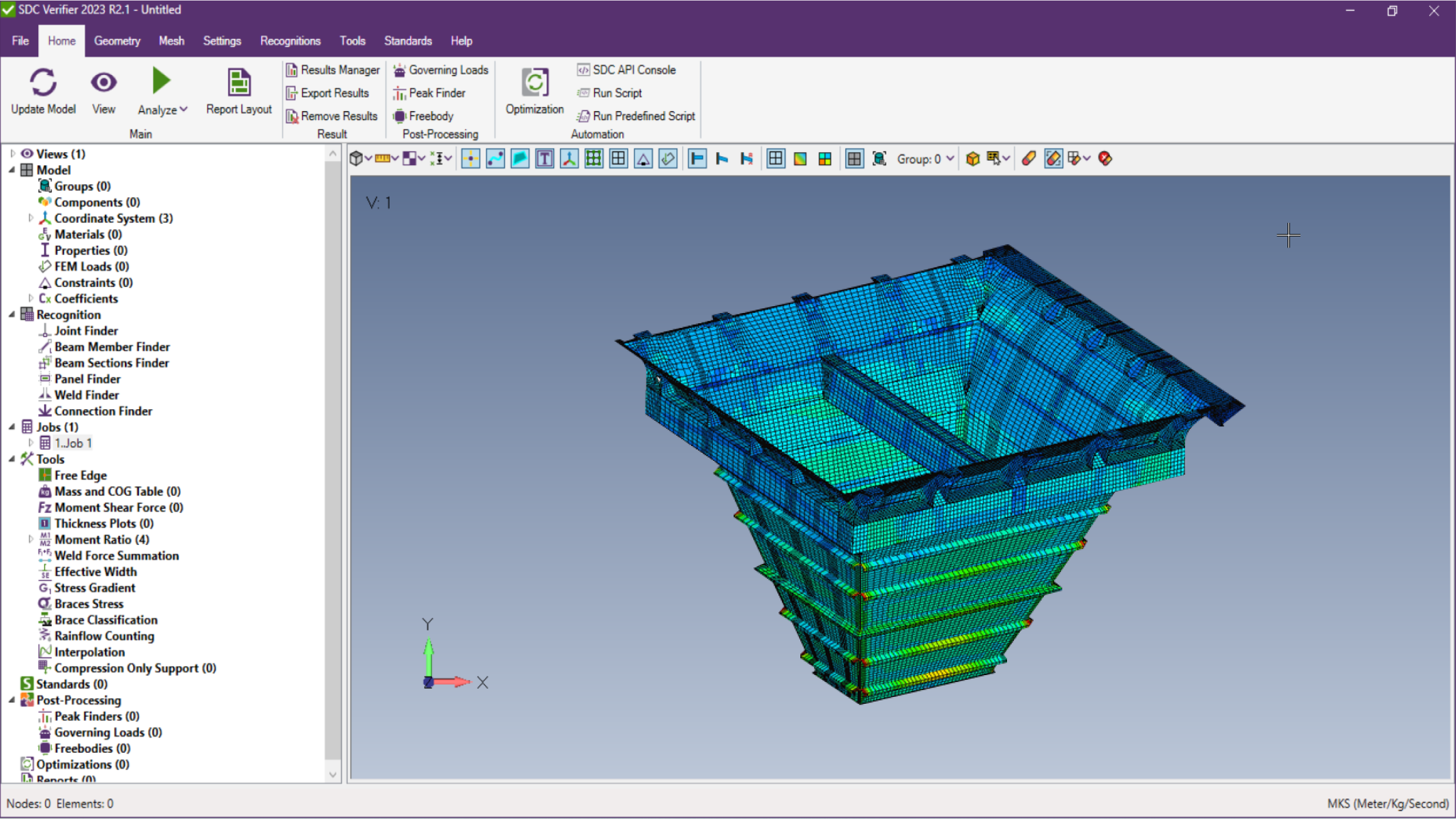
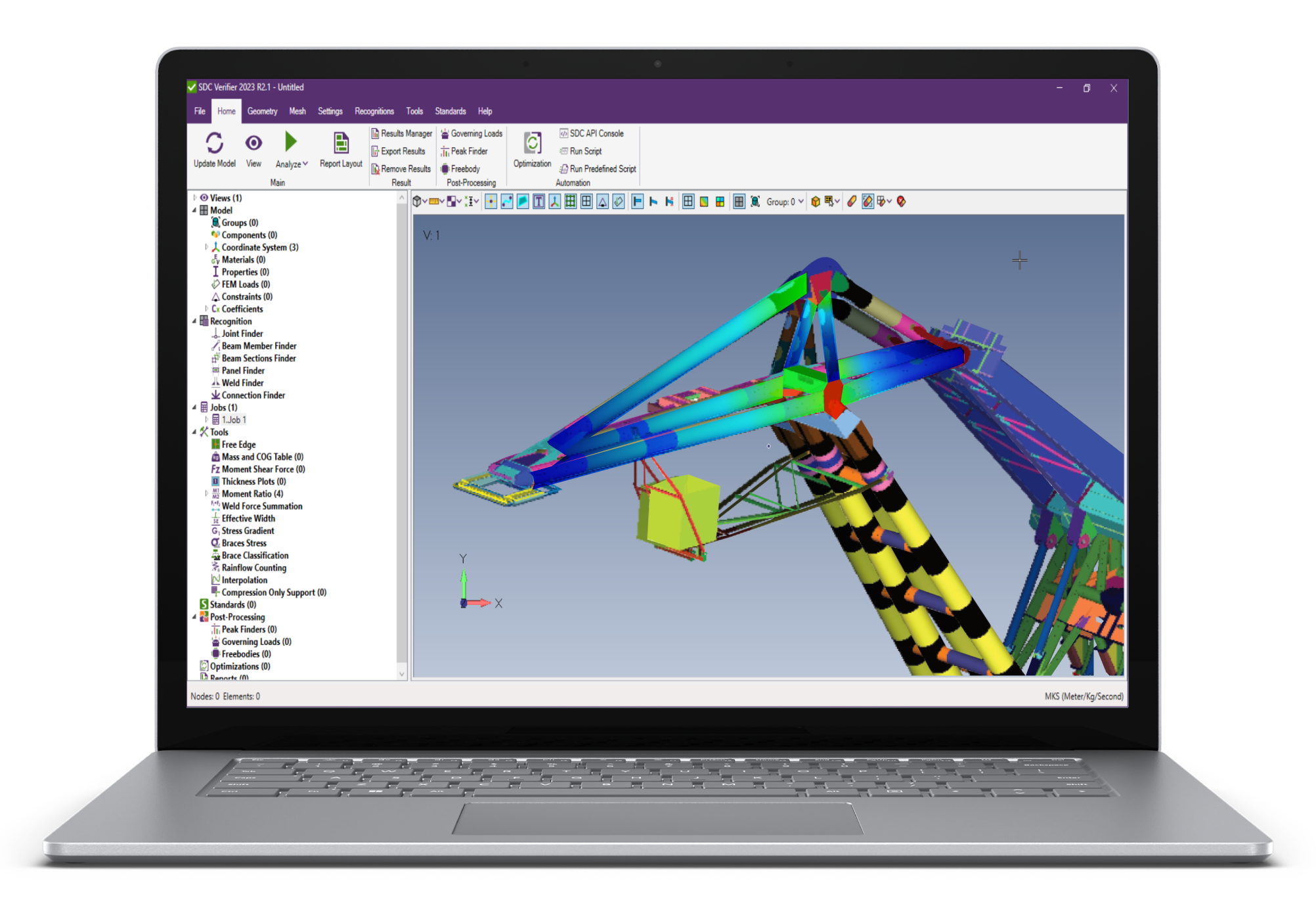
High-fidelity FEA models, which capture intricate details of geometry, can be computationally intensive. As the complexity of the model increases, so do the demands on computational resources—processing power, memory, and time. To mitigate this, techniques such as adaptive meshing, sub-modeling, and multi-scale analysis are commonly used to reduce computational load. Additionally, combining models in structural design and analysis software SDC Verifier can help expedite the process, making it more efficient without compromising accuracy.
This is particularly problematic when working with large assemblies or detailed parts that require high mesh resolution or when simulating scenarios with multiple load cases. Without sufficient computational power, simulations can become impractical or prohibitively expensive.
6. Software Limitations and Compatibility
All mentioned issues with simplification of geometry and others listed above are not always easy to solve with CAD and FEA software. For instance, while CAD software may handle complex, freeform shapes with ease, FEA tools may require these shapes to be converted into simpler forms.
Incompatibility issues such as geometric details, material properties, and feature history, can arise when the CAD software’s file export features don’t fully support the necessary attributes for FEA analysis, leading to the need for manual adjustments or additional intermediate software tools.
Considering all the issues, structural verification software, such as SDC Verifier, helps in ensuring that the geometry transition from CAD to FEA is both seamless and efficient. By offering advanced tools for meshing, geometry simplification, and integration with various CAD systems, SDC Verifier helps mitigate the challenges associated with the transition.
Conclusion
The transition from CAD to FEA is a vital yet intricate step in the engineering workflow, where design geometry undergoes rigorous preparation to ensure accurate analysis. From exporting geometry to simplifying models, meshing, and applying boundary conditions, each stage demands precision and expertise.
Despite challenges such as maintaining accuracy during simplification, ensuring mesh quality, and overcoming software compatibility issues, tools like SDC Verifier significantly streamline the process. By automating key tasks and integrating seamlessly with CAD systems, structural verification software empowers engineers to bridge the gap between design and analysis with confidence, delivering reliable results for even the most complex projects.
