The Foundation of Structural Engineering: Geometry and Its Role in FEA
Geometry lies at the heart of structural engineering, shaping the way we design, analyze, and optimize everything from bridges to components of offshore platforms, jackets, topsides, or mooring systems. In the realm of Finite Element Analysis (FEA), geometry takes on an even more crucial role, as engineers apply it to create accurate models that simulate real-world conditions.
Geometry serves as the foundation for the majority of finite element meshes. Hence, engineers need to possess reliable tools for generating geometry. Without precise geometrical inputs, even the most advanced FEA tools cannot deliver the detailed and reliable results that engineers require to make solid decisions and conclusions. This article delves into the importance of geometry in structural engineering and its indispensable connection to FEA.
The Importance of Geometry in FEA
Geometry is the core of FEA, shaping the creation of finite element meshes and directly influencing the accuracy, convergence, and efficiency of the analysis. Its role extends from defining how models are constructed to how forces and constraints are applied, making it a foundational aspect of simulation.
Geometry and Finite Element Meshes
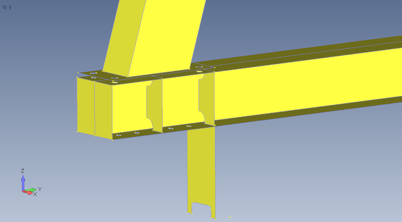
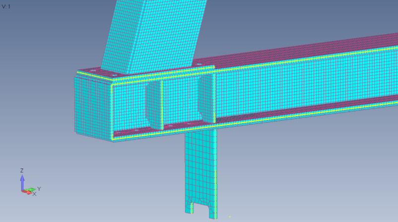
Finite element meshes are derived directly from the geometry of a model, with elements representing discrete segments of the structure. The quality of the mesh—its element size, shape, and distribution—is can be determined by the geometric representation of the structure, depending on the level of geometry preparation.
Bridging the Gap Between CAD and FEA
Geometry acts as a critical link between Computer-Aided Design (CAD) and FEA, enabling engineers to seamlessly transition from conceptual designs to structural evaluation.
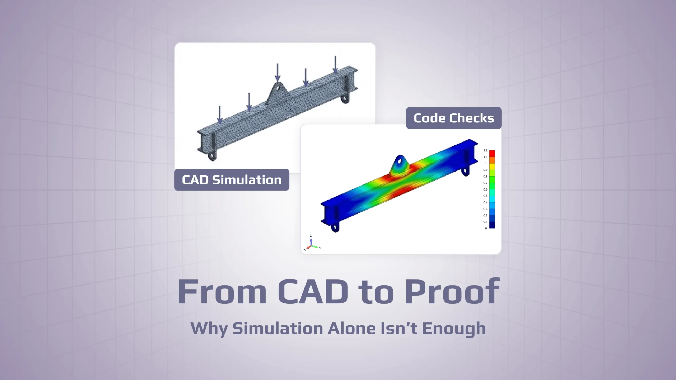
Through this integration, engineers can virtually test designs under simulated conditions before construction begins. Based on the geometry, the engineer can generate mesh, apply material properties and boundary conditions in FEA to predict how a structure will respond to loads, stresses, and environmental factors, identifying potential issues like deformation, stress concentrations, or failure points.
Role in Stress Distribution and Deformation Analysis
Accurate geometric models play a crucial role in predicting stress distribution and nature behavior of the structure. By precisely representing the geometry, engineers can subsequently obtain reliable and detailed stress distribution results and patterns of deformation, ensuring that the design can withstand operational loads.
Balancing Simplification and Detail
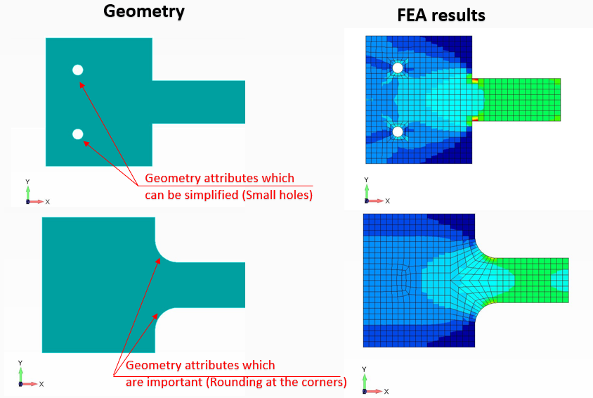
One of the critical moments in FEA is achieving a balance between simplifying geometry for computational efficiency and preserving essential details for analysis accuracy. Simplifications, such as removing small fillets or insignificant features, can reduce element count and computational time. However, it’s crucial to apply engineering judgment when deciding which features to simplify.
For example, retaining features in areas prone to stress concentration, such as fillet radii under bending loads, is vital to ensure accurate analysis and reliable results.
Creating Geometry in FEA Software
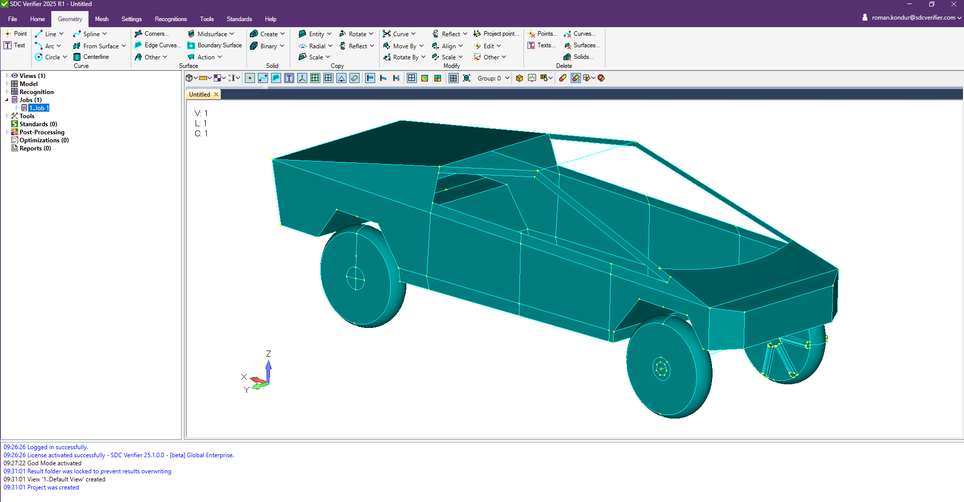
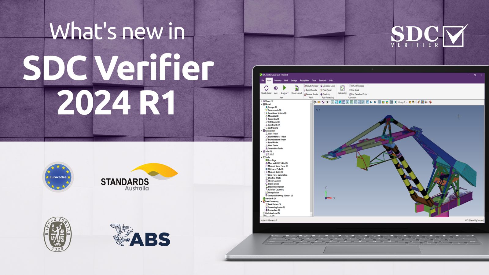
FEA structural analysis software like SDC Verifier allows to create and import geometry before meshing it and applying boundary conditions. The process involves several key stages:
Model Creation

- Lines
Points are the basic building blocks used to construct other geometric entities. Points are defined using coordinate systems to establish precise locations in the model.
Curves are essential for forming surfaces and can be derived from reference points. Curves can also have loads and constraints applied directly. Lines connect points and can be created in various ways, such as between two points, at specific angles, or tangent to curves.
- Arcs, Circles, and Splines
Arcs are defined by endpoints and radius, while circles are defined by center and radius. Both can be tangent to other curves. Splines are created using control points or points the spline passes through. They can be Bezier or B-splines depending on the number of points.
- Surface Creation
Surfaces can be created from curves by defining corners or using curves as boundaries. Midsurfaces are generated between two surfaces of a solid or by connecting surfaces, and can be trimmed, extended, or automatically created.
Boundary surfaces are defined by selecting existing curves. Other methods include extruding, revolving, sweeping curves, or using primitives like planes, cylinders, and spheres.
- Solid Creation
Solids can be created using primitives like blocks, cylinders, cones, and spheres, which can be modified as needed. They can also be formed by extruding, revolving, or sweeping surfaces along a path.
Fillet and chamfer operations add rounded or beveled edges, while shell and thicken operations are used to hollow out or thicken solids. Additionally, solids can be sliced or have faces embedded to create new entities.
Model Modification
Curves and surfaces can be trimmed or extended to meet other entities, and curves can be divided into segments or joined together. Entities can be moved, rotated, or reflected across planes, and scaled or aligned to specific points or curves.
Additionally, points, curves, surfaces, and solids can be copied along vectors or radially, scaled or rotated around vectors, and reflected across planes.
- Copying, Transforming, and Finalizing Geometry
Points, curves, surfaces, and solids can be duplicated along vectors or radially, scaled or rotated around vectors to fit design requirements, and mirrored across planes to create symmetrical models.
Cleanup processes identify and remove extraneous features, ensuring a clean and efficient model.
- Importing STEP Files
SDC Verifier supports the import of geometry in STEP files (.step, .stp), enabling seamless integration of CAD models into the FEA workflow. This ensures compatibility with various design tools and reduces the need for manual geometry reconstruction.
So, creating accurate geometry in FEA software like SDC Verifier is central in generating reliable finite element models. Proper geometry facilitates efficient meshing and boundary condition application, leading to more effective and reliable analysis results.
Challenges with Geometry in Structural Engineering
- Issues with Missing Surfaces or Invalid Elements
When CAD models are imported into FEA tools, missing surfaces, overlaps, or invalid elements often occur. This happens because CAD designs are optimized for visualization or manufacturing, not for analysis. Complex features like fillets, small holes, or thin sections may lead to inconsistencies in the FEA mesh, requiring significant manual cleanup or repair to ensure accurate simulation results.
Specific techniques to address these issues include using the Meshing Toolbox in SDC Verifier, which offers comprehensive tools to prepare geometry before meshing. See in the video how you can easily clean your geometry with SDC Verifier:
- Modeling Intricate Designs
Intricate designs such as curved surfaces, parametric geometries, or thin-walled structures present challenges during meshing. Mesh quality directly impacts the accuracy of results, and complex geometries often necessitate finer meshes, increasing computational time and resources. Automated meshing tools may fail in these cases, requiring manual intervention to create an appropriate element distribution.
Solutions to these challenges include using automated mesh refinement to accurately capture complex features, applying defeaturing techniques to simplify the geometry without losing critical details, and leveraging advanced meshing algorithms that adapt to the geometry’s intricacies.
- Geometry Validation
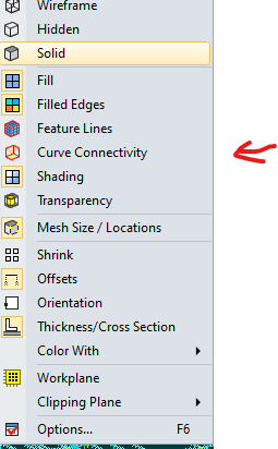
Engineers must validate the imported model by checking for gaps, overlaps, and incorrect boundaries to ensure accurate meshing. Key steps include detecting non-manifold edges, correcting degenerate elements, ensuring watertight surfaces, and using tools like Curve Connectivity to verify proper geometry continuity.
Conclusion
Geometry is the first and the most crucial step of structural engineering and Finite Element Analysis (FEA). From defining meshes to predicting stress distribution and deformation, precise geometric representation is essential for reliable simulations.
Engineers must balance simplification and detail, validate imported models, and address challenges such as missing surfaces or complex designs. By leveraging advanced tools like SDC Verifier, they can streamline geometry creation and modification, ultimately leading to more effective structural analysis.
