
Fatigue and Weld Assessment Support for the MMC240 3D Crane
3
Operating scenario groups assessed
6
Loads applied for each crane position
2
Design standards applied
2
Selected weld configurations optimized below the allowable UF limit
- Client: Motus Technology AS
- Structure: MMC240 3D Crane
- Application: 3D-motion compensated crane for an offshore wind vessel
- Standards: EN 13001 and DNV OS-C201
- Workflow: Ansys Workbench results and SDC for Ansys
The MMC240 3D Crane is intended for operation on an offshore wind vessel across a range of boom positions and operating conditions. The structural response changes with the crane configuration and the inclination of the vessel.
Motus Technology AS retained responsibility for the overall structural verification of the crane. SDC supported the Motus engineering team with fatigue assessment according to EN 13001 and weld strength assessment according to DNV OS-C201.
The work was based on finite element results and load cases defined by the Motus engineering team in accordance with the applicable requirements. SDC for Ansys was used to organize the calculation results, identify governing cases, evaluate fatigue and weld performance, optimize selected weld configurations, and prepare structured reports.
This case study describes the operating positions included in the assessment, the calculation workflow, and the selected results approved for public presentation.
The Project
The MMC240 3D Crane is a 3D-motion compensated crane intended for operation on an offshore wind vessel.
Motus Technology AS engaged SDC Verifier to support the fatigue and weld assessment of the crane under representative operating conditions. 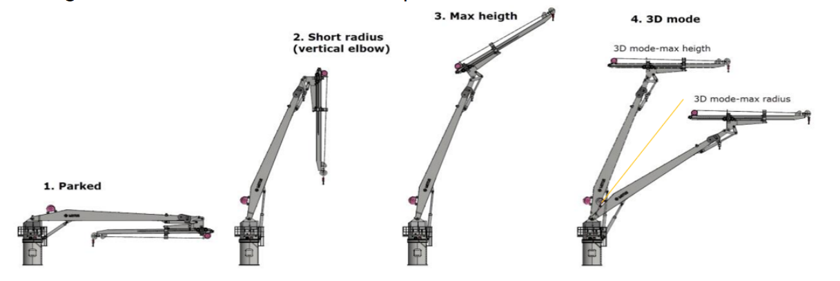
Representative operating positions of the MMC240 3D Crane included in the fatigue and weld assessment.
SDC Verifier scope covered:
- fatigue assessment according to EN 13001;
- weld strength assessment according to DNV OS-C201;
- review of harbor and offshore operating conditions;
- review of several boom outreach and working positions;
- offshore load cases accounting for vessel heel and trim;
- evaluation and optimization of selected weld configurations.
For each crane position, six loads were applied. This required a structured process for organizing the solved load results, creating the required combinations, identifying governing conditions, and reviewing fatigue and weld performance.
Operating positions included in the assessment
The structural demand on the crane changes with its operating position. The assessment therefore covered positions relevant to harbor lifting, offshore lifting, and additional 3D offshore configurations.
Harbor lifting positions
For harbor lifting, the assessed boom positions included:
- parked;
- maximum radius;
- maximum height;
- short radius.
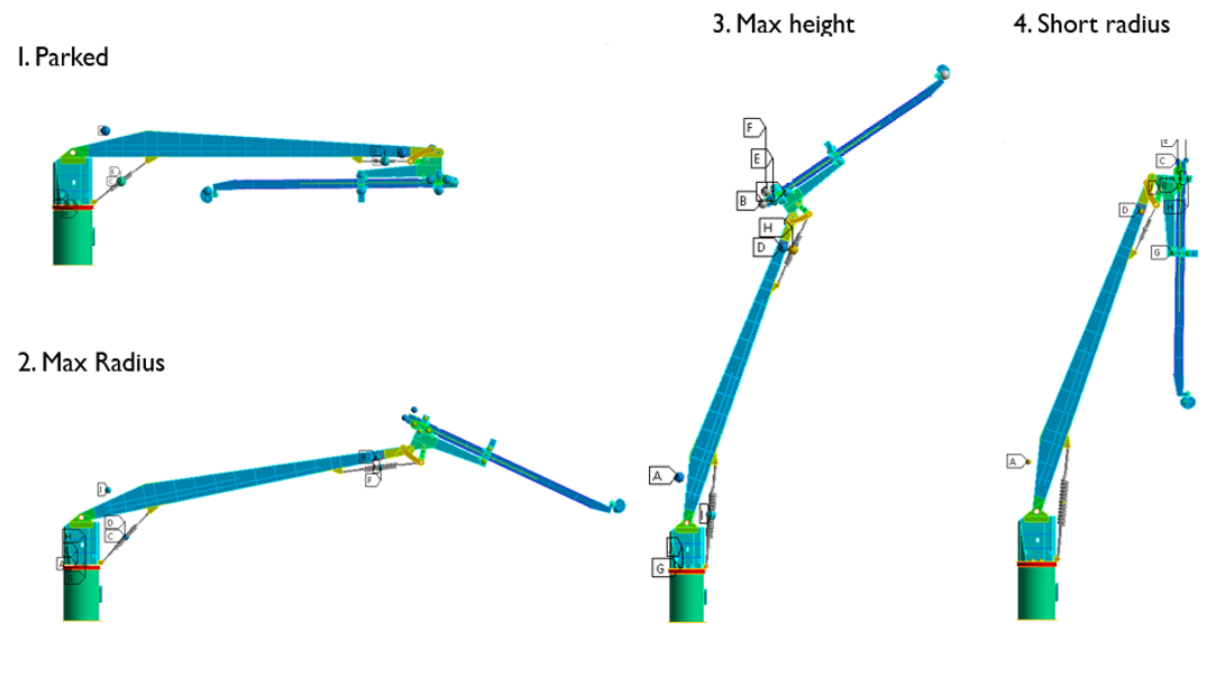
Harbor lifting positions included in the assessment: parked, maximum radius, maximum height, and short radius.
Offshore lifting positions
For offshore lifting, the assessment included:
- parked;
- short radius;
- maximum height.
The corresponding load cases also accounted for vessel inclination through heel and trim.
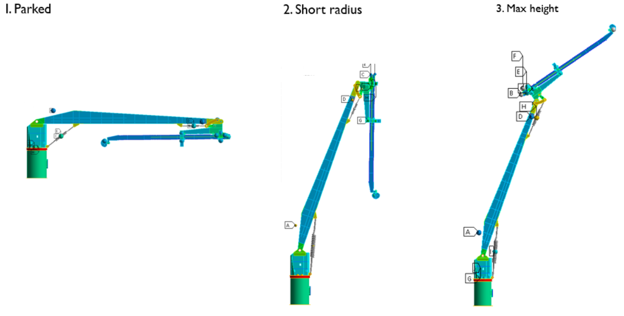
Offshore lifting positions included in the assessment: parked, short radius, and maximum height.
Additional 3D offshore positions
The offshore scope also included three groups of 3D boom configurations:
- maximum height;
- middle outreach;
- maximum radius.
Each group was assessed at minimum, middle, and maximum variants.
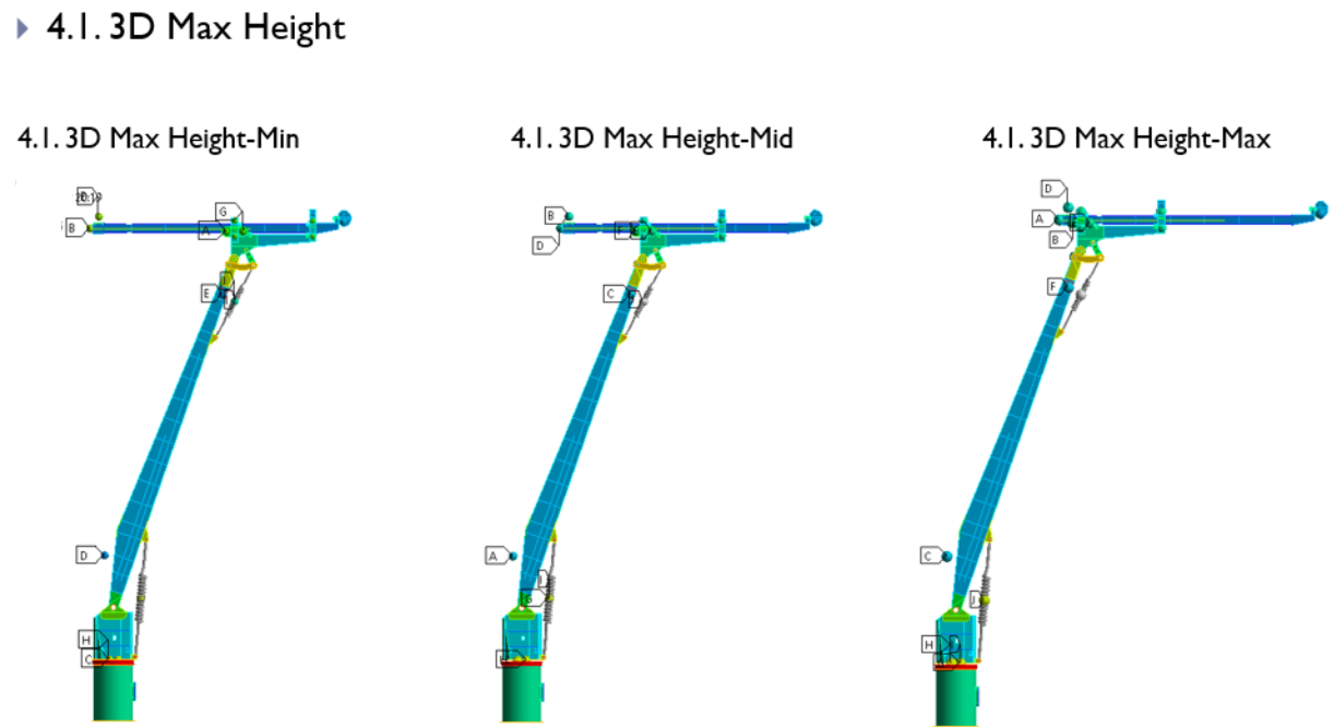
3D maximum-height offshore configurations included in the assessment: minimum, middle, and maximum variants.
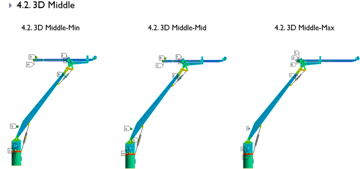
3D middle-outreach offshore configurations included in the assessment: minimum, middle, and maximum variants.
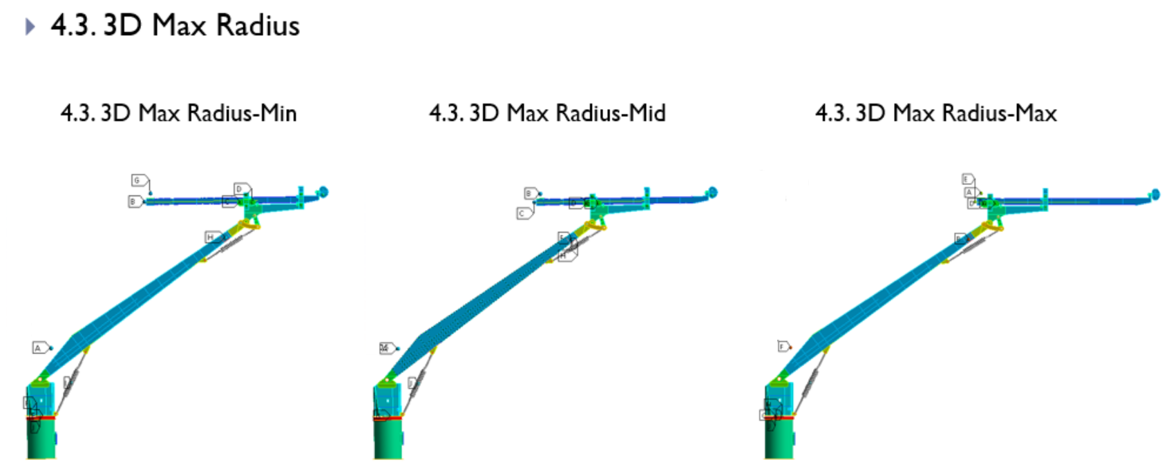
3D maximum-radius offshore configurations included in the assessment: minimum, middle, and maximum variants.
Together, these configurations formed the basis for organizing the relevant load combinations and reviewing fatigue and weld strength results in SDC for Ansys.
The assessment workflow
The project combined solved Ansys Workbench results with standards-based assessment and post-processing in SDC for Ansys.
Ansys Workbench results
The assessment used the finite element model, individual loads, constraints, and solved load results provided by Motus.
These results formed the basis for the fatigue and weld assessment performed by SDC.
SDC for Ansys
SDC for Ansys was used to:
- perform fatigue summation checks according to EN 13001;
- perform weld strength checks according to DNV OS-C201;
- evaluate and optimize selected weld configurations;
- prepare model setup and results reports.
From solved loads to assessment results
The calculated load results were organized through a clear sequence.
Step 1 — Individual Loads
Each Individual Load represented a separate solved FEM load result together with its relevant constraint.
Step 2 — Load Sets
Load Sets combined the Individual Loads into the required operating conditions for the relevant crane positions and load directions.
Step 3 — Load Groups and Fatigue Groups
Load Groups were used to identify the governing results across the considered combinations.
Fatigue Groups organized the relevant load groups and fatigue histories used in the EN 13001 assessment.
SDC for Ansys functions used in the assessment
The work required more than calculating a final value. Engineers needed to identify welded details, organize a large number of load cases, determine the governing conditions, evaluate local result peaks, and prepare structured reports.
SDC for Ansys was used for:
- Weld Finder, to identify welds in the model;
- automatic creation of load sets, load groups, and fatigue groups;
- Governing Loads, to identify the critical load combinations;
- Peak Finder, to identify result peak zones and summarize them in plots and tables;
- contour plots and result tables for technical review;
- evaluation and optimization of selected weld configurations;
- automated preparation of model setup and results reports.
This reduced manual work in pre-processing, post-processing, result review, and report preparation.
Results
The project produced fatigue assessment results according to EN 13001 and weld strength assessment results according to DNV OS-C201.
SDC for Ansys allowed the engineering team to organize the calculated results, identify governing cases, review the structural zones included in the assessment, and evaluate selected weld configurations requiring further attention.
Fatigue assessment according to EN 13001
The fatigue assessment covered the operating cases and load combinations defined by Motus.
The overview below shows the main structural zones included in the fatigue assessment without displaying detailed fatigue utilization results.
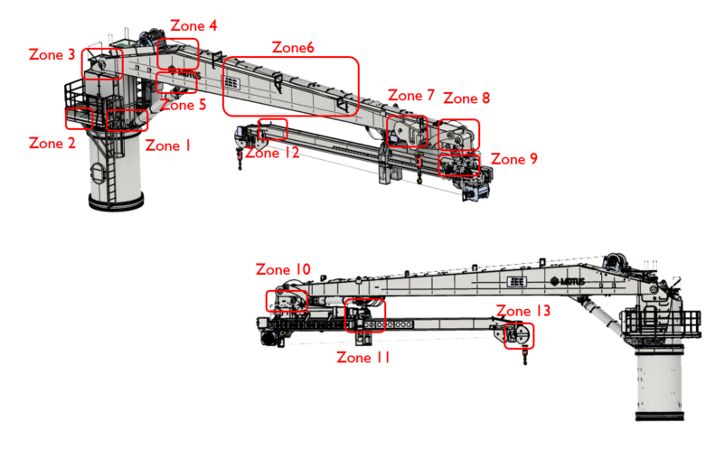
Main structural zones included in the EN 13001 fatigue assessment.
The reviewed locations included connections at the crane column, boom structure, lifting mechanism, and end assemblies.
The fatigue results enabled the project team to identify zones requiring further detailed analysis within the wider structural verification process managed by Motus.
Weld strength assessment according to DNV OS-C201
The weld strength assessment was performed according to DNV OS-C201.
For this assessment, the utilization factor represents the relationship between the calculated forces in a weld and its resistance according to the standard. A calculated utilization factor above the allowable limit indicated that the selected weld configuration required further evaluation.
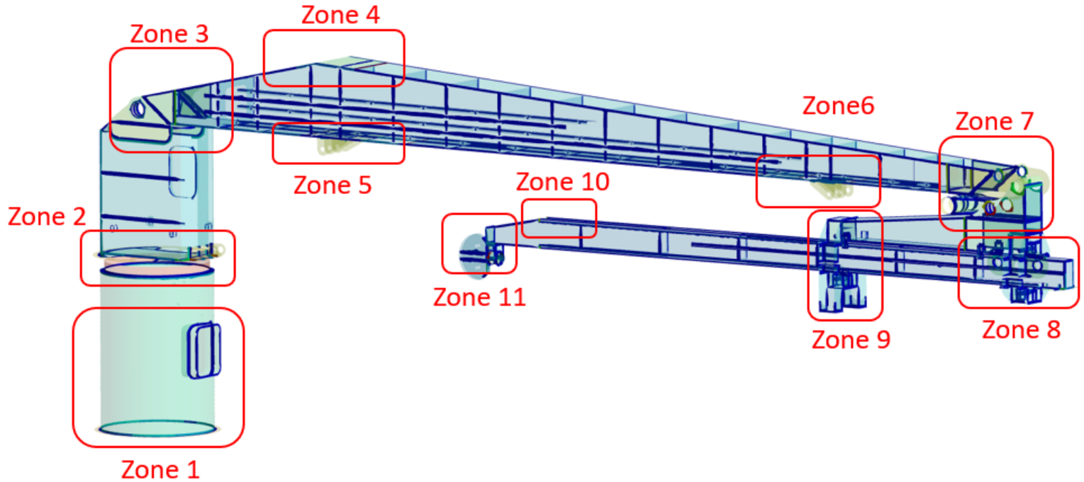
Main structural zones included in the DNV OS-C201 weld strength assessment.
The reviewed zones covered welded details at the crane column, boom, secondary lifting structure, and end assemblies.
Optimization of selected weld configurations in Zone 4
The weld strength assessment identified two selected weld configurations in Zone 4 with calculated utilization factors above the allowable limit.
The original utilization factors were:
- 1.06 for a selected double fillet weld configuration;
- 1.09 for a selected full penetration weld configuration.
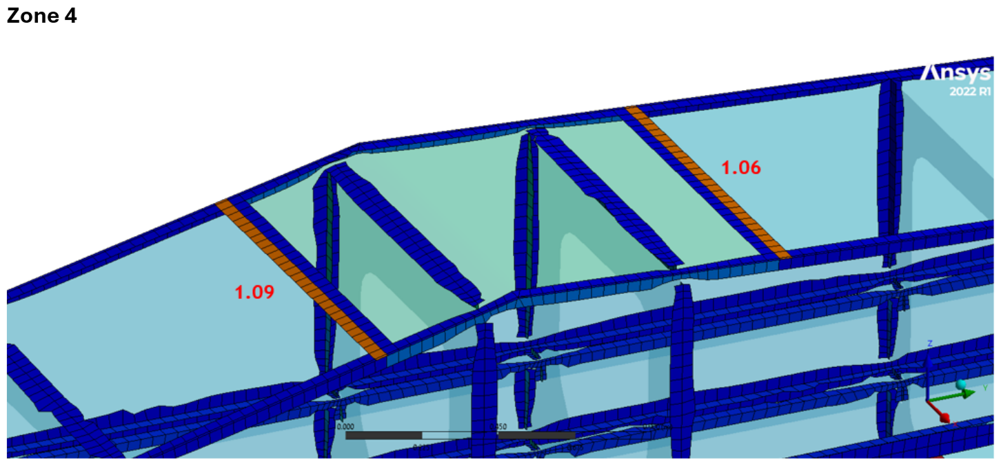
Zone 4 welded details where the original dimensions resulted in calculated utilization factors above the allowable limit.
SDC Verifier supported the evaluation and optimization of these weld configurations in SDC for Ansys. The optimized results were compared with the original weld definitions.
Utilization factors before and after weld optimization
| Weld configuration | Original UF | Optimized UF |
|---|---|---|
| Selected double fillet weld | 1.06 | 0.88 |
| Selected full penetration weld | 1.09 | 0.87 |
In both cases, the optimized weld configuration reduced the calculated utilization factor below the allowable limit of UF < 1 in the DNV OS-C201 weld strength assessment.
The outcome
Motus Technology AS retained responsibility for the overall structural verification of the MMC240 3D Crane. SDC Verifier supported the Motus engineering team with fatigue assessment according to EN 13001 and weld strength assessment according to DNV OS-C201.
Using Ansys Workbench results and SDC for Ansys, the project team was able to:
- organize the load cases defined by Motus;
- review fatigue and weld strength results;
- identify governing cases and zones requiring further analysis;
- optimize selected weld configurations with utilization factors above the allowable limit;
- prepare structured model setup and results reports.
The workflow reduced manual work in result processing, standards-based assessment, weld evaluation, and report preparation.
It also provided clear calculation outputs that Motus could use as part of the wider structural verification process.
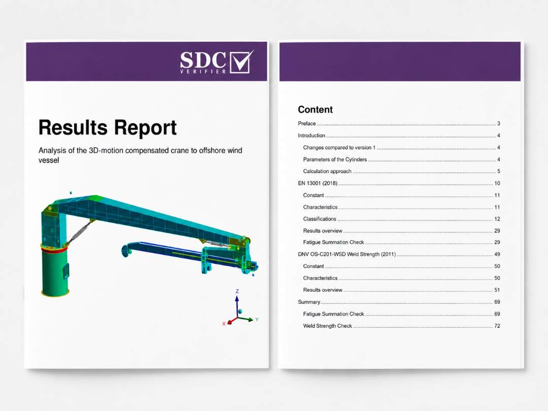
The project included structured model setup and results documentation.
The Results Report covered:
- the calculation approach;
- EN 13001 fatigue assessment;
- DNV OS-C201 weld strength assessment;
- reviewed structural zones;
- selected weld optimization results;
- final calculation summaries.
SDC Verifier for crane and lifting structure verification
SDC for Ansys was used as the standards-based verification and post-processing environment for the MMC240 analysis. Working from solved FEM results, the engineering team could organize load combinations and fatigue histories, identify governing results, review welded details, evaluate revised configurations, and produce structured calculation reports in one workflow.
For cranes and other lifting structures, this approach supports technical review across multiple operating positions and load combinations without relying on manual result handling for every individual case.
Need to verify a crane or lifting structure?
SDC Verifier engineers can assess fatigue, weld strength, and critical load cases for cranes and lifting structures using your FEM results and the required design standards.
Discuss Your Verification Project