
How X1 Wind Accelerated DNV Verification for Floating Wind Platform with Up to 1.2 Million Elements


1.2M
finite elements in the largest model
~120
load cases checked in one workflow
8h → 1–2h
per column buckling check
- Large floating wind models verified from Ansys results. Columns, TLP components, and the heave plate were assessed using models containing up to 1.2 million finite elements.
- DNV buckling and yielding workflows automated. DNV-RP-C201 and DNV-RP-C202 checks for plate and shell buckling successfully performed, including custom checks for Von Mises and shear stress evaluation.
- Repeated design checks became much faster. Around 120 load cases were processed in a single flow, while column buckling verification was reduced from eight hours to less than two hours.
The X100 is X1 Wind’s pre-commercial floating wind platform, built to validate its PivotBuoy technology at full scale offshore.
The lightweight, tripod-shaped platform combines Single Point Mooring (SPM) for easy installation with the stability and weight savings of a Tension Leg Platform (TLP) mooring system. Paired with a downwind configuration, it passively weathervanes with wind direction, eliminating the need for active yaw mechanisms.
This design cuts primary steel weight by up to 50% versus traditional floating technologies, while the TLP’s vertical mooring lines sharply reduce seabed footprint compared to catenary systems—minimizing environmental impact.
The X100 will be deployed at the PLEMCAT test site in Catalonia, Spain. It recently received a Statement of Compliance (SoC) for Basic Design from DNV, independently verifying X1 Wind’s calculation methods, structural design, and the platform’s ability to withstand extreme offshore conditions over a 25-year service life. Depending on required detail, the FE models ranged from roughly 300,000 to 1.2 million elements.
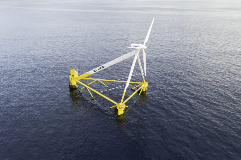
Image: X1 Wind’s X100 floating wind platform
Verify large offshore models without rebuilding the checks after every design iteration
Automate plate and shell buckling checks, process load-case envelopes, and update verification results directly from Ansys after each model rerun.
Book a Demo
Project overview
| Company | X1 Wind |
| Project | X100 floating wind prototype |
| Structure | Floating wind platform |
| Components | Columns, TLP components, and heave plate |
| FE model size | Approximately 300,000–1.2 million elements |
| Verification flow | Approximately 120 load cases |
| Plate buckling | DNV-RP-C201 |
| Shell buckling | DNV-RP-C202 |
| Additional checks | Von Mises and shear stress limits |
| Software | Ansys; SDC for Ansys |
| Deployment and testing |
PLEMCAT, Mediterranean Sea, Spain |
The bottleneck was repeated post-processing
Running the structural analysis was only one part of the engineering workload. The larger bottleneck appeared after the Ansys solver had finished.
For a single column, the manual buckling workflow required approximately eight engineering hours:
- five to six hours to extract
σxandσyresults from Ansys; - approximately one hour to check shear stress for the individual panels;
- around 30 minutes to prepare the required files.
Each structure typically included approximately 12 to 15 shell panels assessed according to DNV-RP-C202 and another 8 to 10 plate panels assessed according to DNV-RP-C201.
The columns were particularly demanding because they were subjected to more loads and represented some of the largest FE models.
The main cost appeared during design iterations. When engineers changed plate thickness, reinforcement, unsupported spans, or component geometry, the Ansys analysis had to be rerun. Under the manual process, much of the stress extraction and preparation work then had to be repeated.
Building a reusable verification workflow
X1 Wind connected SDC for Ansys directly to the existing Ansys results and moved the buckling and yielding checks into a reusable verification process.
The engineering team used the software to:
- perform plate buckling checks according to DNV-RP-C201;
- perform shell buckling checks according to DNV-RP-C202;
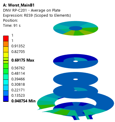
DNV-RP-C201 plate buckling results across multiple analyzed panels in SDC for Ansys. Maximum utilization shown: 0.692.
- evaluate multiple panels within the same model;
- process loads stored across successive time steps;
- assess approximately 120 cases in one workflow;
- create load-case envelopes for buckling and yielding;
- identify governing load cases and critical structural areas;
- evaluate von Mises and shear stresses using custom verification rules;
- update the checks after new Ansys results became available.
The custom yielding code was configured inside SDC Verifier to compare calculated von Mises and shear stresses with the applicable material limits.
Instead of manually extracting values for each panel and rebuilding separate calculations, the engineers could work directly with the results already available from Ansys.
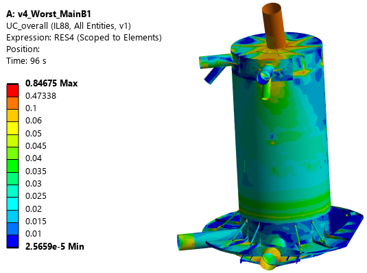
Yielding utilization across the analyzed floating wind structure using a custom SDC for Ansys check. Maximum utilization shown: 0.847.
Load-case envelopes replaced case-by-case review
X1 Wind used load-case envelopes for both buckling and yielding checks.
This allowed the team to identify the governing load cases across the analyzed results rather than reviewing each case independently. Engineers could focus on the critical combinations and structural regions requiring attention.
Approximately 120 cases could be processed within one sequence.
Verification became part of the design loop
The workflow was most valuable when a check identified an overstressed or buckling-critical region.
The engineering team first evaluated the magnitude and structural significance of the result. Depending on the issue, the design could then be modified by:
- reducing an unsupported span;
- adding local reinforcement;
- increasing plate thickness;
- changing the component geometry.
The revised structure was rerun in Ansys, after which SDC Verifier updated the existing checks using the new results.
This created a repeatable process:
1. Run the structural analysis in Ansys
Generate updated stress results for the current design.
2. Verify buckling and yielding in SDC for Ansys
Process the relevant panels, load cases, and material limits.
3. Identify governing structural areas
Review the critical utilization values and load combinations.
4. Modify the design
Adjust spans, reinforcement, thicknesses, or geometry.
5. Rerun and update the checks in SDC for Ansys
Reuse the verification setup with the revised Ansys results.
The team no longer had to recreate the checking process after every relevant model change.
Results
A single-column buckling check fell from eight hours to one or two
The manual buckling analysis for one column took approximately eight hours.
With SDC for Ansys, the same process could be completed in one to two hours.
Most of the saving came from eliminating repeated extraction and preparation of σx, σy, and shear stress values for individual panels.
Repeated iterations no longer required another full manual workflow
Under the previous approach, each significant design update could trigger another eight-hour verification cycle.
With the reusable SDC for Ansys flow, engineers could modify the structure, rerun Ansys, and refresh the checks without rebuilding the verification process.
Across multiple iterations, this saved days of repeated engineering work.
Approximately 120 cases were processed in one workflow
Loads stored across successive time steps could be evaluated together, with load-case envelopes identifying the governing buckling and yielding results.
This reduced the amount of case-by-case review required from the engineering team.
Models of up to 1.2 million elements were handled consistently
The same procedure was applied to FE models ranging from approximately 300,000 to 1.2 million elements.
This gave the team a consistent verification process across structures with different sizes and levels of detail.
Engineers gained clearer visibility into structural margin
X1 Wind’s previous manual checks were more conservative. The SDC for Ansys process provided a more detailed view of the available structural margin across the model.
This supported better-informed decisions about whether a critical area required additional thickness, reinforcement, a geometry change, or no modification.
The workflow contributed to weight optimization, although X1 Wind has not yet quantified the resulting material or weight reduction.