Recognition tools are used for automatic detection of different structural elements (joints, connections, beams, plates, welds) and further use them in checks according to industry rules and regulations or custom checks.
Construction safety is a crucial requirement for engineers’ tasks. To avoid collapse, each construction must be verified according to global and local industry standards. Performing checking according to standards is quite a complicated procedure. Besides the massive amount of rules to calculate (which depend on different shapes, materials, and other criteria), additional structure characteristics should be defined:
For Beam Buckling – beam buckling length;
For Plate Buckling – plate width, length, and direction;
For Fatigue – welds classifications.
Manual defining these characteristics is possible only for small models, but still is time-consuming. For big models like vessels, it is impossible, for example, in ship models where 100-200 thousand plates are checked using specific standard.
We believe that characteristics detection routines can be automated. For that purpose, SDC Verifier implements a set of Recognition Tools.
Joint Finder
Joints Finder is a powerful tool that helps to find and automatically detect different types of joints (1D, 2DY, 2DZ, 3D, etc.) that are used to find beam member lengths and connections for Joint Check. It is used by Beam Member Finder tool to recognize beam member length in 2 directions and by Joint Checks.
There following types of Joints are recognized automatically:
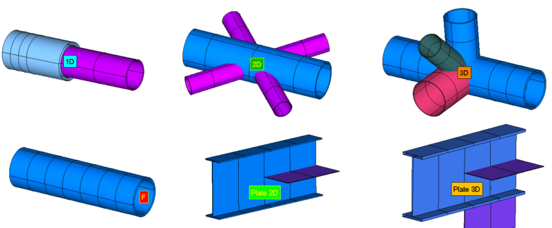
1D Joints – connection of 2 beam properties that lies on a straight curve. Can be used when setting up weld classification;
2D Joints – recognize 2D Y and 2D Z joints and Undefined (limit length in 1 direction);
3D Joints – limit length in both directions;
Plate 2D, 3D, Undefined – identify beam connections associated with plate elements. For members treated as plate-supported, an effective length factor of 0.01 may be assigned by default.
Beam-Plate Joints – a beam that is connected to a plate and is parallel to a plate normal vector with a tolerance = TOLERANCE ANGLE defined in Settings;
User Joints – the joints defined by a user;
Free Joints – the node which is connected only to one element.
Automatic Joints Detection
Joints Finder Tool Interface
You have three options to automatically detect all joints:
Remove All – removes all existing joints and performs joint detection from scratch;
Keep only Modified (default) – joints that were modified by user are kept, the rest are removed and tools perform automatic detection of other joints;
Keep all Existing – all existing joints are kept, Joint Finder will look for new joints;
Joints Finder Tool Video
Reviewing and exporting joints
Before using recognized joints in member or connection checks, review their types and locations. Incorrect joint classification can affect member segmentation and the parameters used in subsequent verification.
Edit joint types. . ). Selecting a node applies the type to all elements connected to it.
Find joints. Filter the table by nodes or by joint type, .
Plot joints. Plot joints of selected types, with element and node ID labels and 2D joint axes.
Export joints to nodal or elemental components.
Since SDC Verifier 2026 R2, Joint Finder data can be added to Report Designer. Recognized joints are then documented in the same calculation report as the checks that use them.
Connection Finder
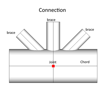
Connection Finder automatically detects connections and their dimensions in the FE model. It is based on Joint Finder: each connection is the set of elements connected at a joint node. These elements are split into a chord and braces:
Chord: non-welded elements that form a straight line.
Braces: elements welded to the chord at the joint node. Each brace is the single element connected to that node.
Chord and braces at a tubular joint
Connection types
Connection Finder recognizes four connection types:
Circular Tube: all braces and chord elements have circular tube sections.
Rectangular Tube: all braces and chord elements have rectangular tube sections.
I-Beam: all braces and chord elements have I-beam sections.
Combined: at least one brace or chord section differs from the others.
Multiplane (3D) connections are split into plane (2D) connections. When braces sit on both sides of the chord, they are listed as Upper and Lower.
Reviewing connections
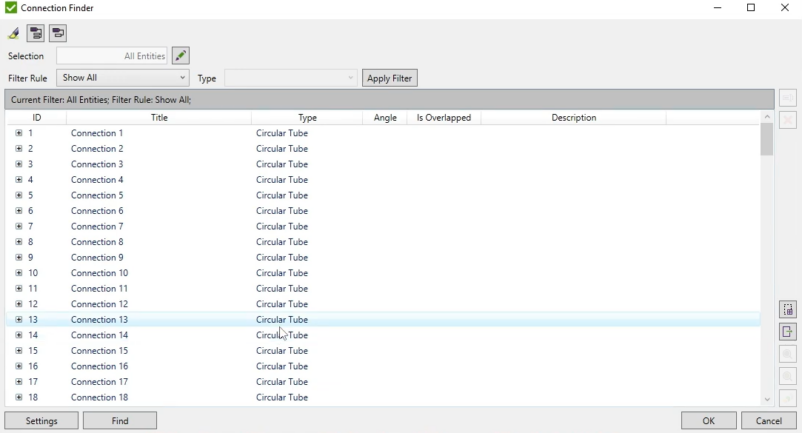
For each connection, the table shows the connection type, its chord and braces, and their cross-section dimensions. Before applying connection checks, verify the recognized chord and brace geometry, cross-section dimensions, and connection grouping. Pay particular attention to multiplane and overlapping connections, where recognition settings can affect how braces are grouped.
You can:
Filter by model selection or by rule. Rules are Show All, Connection Type, and Show Overlapped, which lists connections where at least one brace overlaps another.
Since SDC Verifier 2026 R2, Connection Finder data can be included in Report Designer, allowing recognized connection information to be documented alongside structural verification results.
Connection Finder interface
The Brace Stress Tool calculates axial, in-plane bending and out-of-plane bending stresses in braces from the forces at the joint and the section properties. Since 2026 R2, it also calculates elastic and plastic buckling stresses. In SDC Verifier 2026 R2, the Brace Stress Tool was extended to calculate elastic and plastic buckling stresses. Supported API, ISO, and NORSOK connection checks were updated to support plastic buckling stress values.
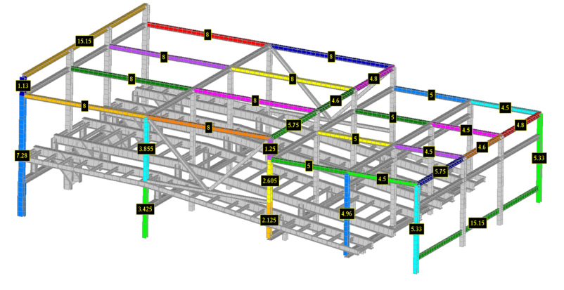
Beam Member Finder automatically recognizes beam members and determines their lengths in the local Y, Z, and torsional directions.
Automatic Beam Detection in FEA Model
Automatic Beam Member Recognition
Beam Member Finder uses recognized joints to identify beam members and their sub-members. Member lengths are determined from the recognized joint locations rather than simply from individual element lengths or mesh density.
The tool recognizes three length directions:
Y length — member length in the local Y direction.
Z length — member length in the local Z direction.
Torsional length — member length used for torsional buckling considerations.
Beam Member Finder tool interface
If a beam member contains intermediate joints, it can be divided into sub-members. The Break Joint Options control which types of joints split members in the Y, Z, custom, and torsional directions. Engineers can review the recognized segmentation, add or remove break joints, and manually adjust member or sub-member lengths when necessary.
Reviewing Recognition Results
Review recognized joints, member segmentation, and local element orientations before using the results in structural verification.
By default, plate joints split members in the Y and Z directions, but not in torsion. The effective length factor may be set to 0.01 for plate-supported members. This is a default assumption, not proof of actual restraint, so engineers should verify the boundary conditions and effective-length assumptions.
Filtering by length, selection, and element orientation helps identify members requiring review. Inconsistent local Y-axis orientations can also affect the Cb factor used by the Moment Ratio Tool. Correct element orientation in the FEA model where necessary.
Member Properties and Verification Parameters
Beam Member Finder lets engineers edit member lengths, length factors, and Cm Type, individually or in groups using filters. Cm Type is used to calculate the Cm moment reduction factors specified in API RP 2A, ISO 19902, and NORSOK N-004 member checks..
Recognized member data supports the following verification checks:
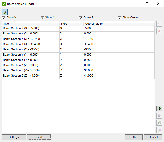
Beam Section Finder helps to group line elements (1D) by planes. It is very similar to Panel Finder, but sections are recognized as beams/bars instead of plates. It is used to improve user experience in the selection process with selectors.
Beam Sections Finder Interface
Panel Finder
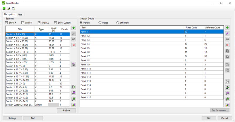
Plate buckling checks calculations are based on plate dimensions from the Panel Finder tool. It works on any plated model and is especially useful for ship hulls and offshore structures.
Panel Finder organizes the model in four levels:
Section: elements grouped by plane: X (YZ plane), Y (XZ), Z (XY) or Custom (inclined or curved).
Panel: elements bounded by shells from other sections. Each panel contains plates and stiffeners.
Plate: plate elements bounded by stiffeners.
Stiffener / Girder: line or plate elements that support a panel against buckling.
Automatic Plates Detection in FEA Model
Engineers can visualize recognized sections, panels, and plates, including inclined and curved regions. When automatic recognition does not reflect the intended geometry, plates can be added, removed, merged, or modified manually. Plate dimensions should be reviewed before they are used in buckling calculations.
Panel Finder Tool Interface
Panel Finder Video Tutorial
Standards that use Panel Finder results
The applicable buckling check depends on the plate geometry and the scope of the selected standard. Recognizing a plate or curved panel does not automatically establish that every listed check is applicable to it.
Weld fatigue checks and weld strength checks need two things FE results don’t provide: where the welds are, and the stresses in each weld’s own directions. Normal and shear stresses parallel and perpendicular to a weld have different allowable fatigue stresses, so element stresses have to be rotated into weld axes first.
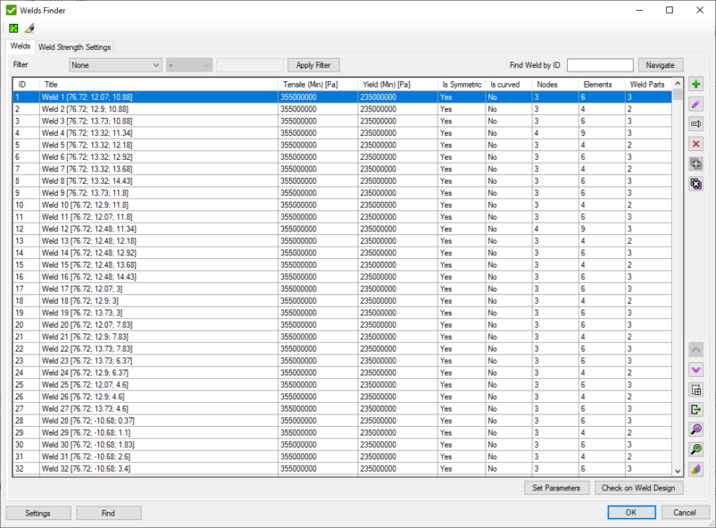
Weld Finder automatically recognizes welds and prepares the data required for fatigue and weld strength verification. For fatigue calculations, elemental stresses are transformed into weld directions. For weld strength checks, stresses are calculated from nodal forces and moments using the specified weld dimensions.
Automatic Weld Detection in FEA Model
During recognition, Weld Finder automatically classifies weld parts as welded or non-welded based on model geometry and element properties. This classification should be reviewed against the intended weld design before verification.
T-weld: the part that doesn’t lie in the plane of the others is welded.
Other welds: the thinnest part is welded. If all parts are equally thick, all are set as non-welded.
After recognition, Weld Finder checks the welded/non-welded part classification and identifies connections that may require manual review. This includes welds where all parts are classified as welded or all as non-welded. Like Joint Finder, it offers Remove All, Keep only Modified and Keep All Existing when you rerun it.
Fatigue: Weld stresses
When an element belongs to multiple welds, such as at weld intersections, the stress orientation is based on the last weld in the Weld Finder list. Engineers should review these regions before using the calculated stresses for fatigue verification.
Weld Finder Tool Interface
Weld strength
Unlike fatigue checks based on elemental stresses, weld strength verification requires the weld type and dimensions to be defined. These properties are used to calculate weld stresses from nodal forces and moments. Weld Finder supports the following four weld types:
Double full penetration: dimensions follow from the part thickness.
Double partial penetration: set the leg sizes and penetration depth; the throat is calculated.
Double fillet: set the legs or the throat (a); the other follows.
Single fillet: the same, plus the weld side.
Hot Spot Stress
For hot spot fatigue assessment, engineers can enable Hot Spot Stress calculations for selected weld parts and define reference point locations. The calculation is disabled by default and must be configured before the results can be used for fatigue verification.:
Distances: a multiple of plate thickness (t) or a custom value. The defaults follow the IIW fatigue recommendations (IIW-1823-07, Dec 2008).
Calculation: the hot spot stress is calculated at the weld toe. The weld toe location depends on the specified weld geometry. If the vertical weld leg size is not defined, Hot Spot Stress is calculated at the intersection of the weld parts instead of the weld toe. Engineers should verify the reference point locations before evaluating fatigue results.
Mesh checks: a mesh-validity check warns when reference points fall on the same element, or when the first point lies on the weld part itself.
Plots: show the reference points and weld throats on the model, so you can verify the setup visually.