In-Depth Guide: Conducting Beam Member Checks According to ASME BTH-1-2023
In the design of Below-the-Hook lifting devices, compliance with stringent safety standards is critical. Every engineering decision impacts not only the structural integrity of the equipment but also operational safety and regulatory compliance.
With the introduction of the ASME BTH-1 (2023) standard, the complexity of member checks has increased, demanding a more efficient way to validate designs.
In this article, we’ll walk through how SDC Verifier streamlines these member checks, combining theoretical calculations with Finite Element Analysis (FEA) to deliver fast, accurate results—helping engineers eliminate manual errors and ensure their designs meet every requirement.
Overview of ASME BTH-1 Standard (2023)
The ASME BTH-1 (2023) standard provides a comprehensive framework for the design of Below-the-Hook lifting devices. It outlines the criteria for various structural members, including symmetric I-shapes, channels, circular and rectangular tubes, as well as bars. The standard emphasizes the need for rigorous evaluation of structural integrity and load-bearing capacity, ensuring that these devices can withstand the operational stresses they are exposed to during lifting operations.
For engineers, adhering to ASME BTH-1 is critical. The standard not only ensures compliance with safety and performance requirements but also aligns designs with globally recognized best practices. It focuses on preventing structural failures, particularly under dynamic loading conditions, by specifying the necessary checks for member slenderness, lateral-torsional buckling, and other key parameters. By following this standard, engineers can guarantee the reliability and durability of their lifting devices, maintaining safety throughout the equipment’s service life.
Spreader Beam Example: Inputs and FEA Model Setup
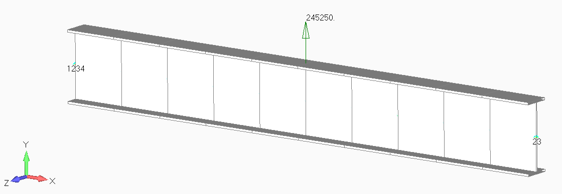
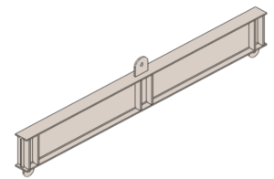
For this example, a spreader beam designed for a 25-ton rated load is analyzed using SDC Verifier, with all checks performed according to ASME BTH-1 (2023). The beam section selected for this design is an IPE 600 made from S275 steel, with a length of 4.5 meters. The design falls under Category B, which requires a nominal design factor of 3, ensuring adequate safety margins under operational loads.
 Key Parameters
- Beam section: IPE 600, S275 structural steel.
- Length: 4.5 meters.
- Design Category B: Nominal design factor of 3.
FEA Model Setup in SDC Verifier
The FEA model is structured to reflect real-world conditions, incorporating both material and geometric properties, as well as applied loading and boundary conditions. All critical input parameters, such as the beam’s material yield strength and cross-sectional properties, are predefined within the model. Loads are applied as concentrated forces, consistent with the lifting capacity, while constraints are imposed to replicate the boundary conditions during operation.
Manual inputs and hand calculations are used to cross-verify key outputs to ensure model accuracy. For instance, the effective net tensile area and lateral bracing configurations are input manually based on design requirements from the standard. Hand calculations also validate critical values such as maximum bending moment and stress. This process guarantees that the FEA results align with theoretical expectations, especially for stress distribution and member utilization.
Recognizing Beam Members in SDC Verifier
The accurate recognition of beam members is critical when setting up an FEA model in SDC Verifier. The software’s Beam Member Finder tool is designed to automatically identify 1D beam elements within the model, ensuring that the correct structural members are evaluated in accordance with ASME BTH-1 (2023). This step is essential for defining how loads and boundary conditions are applied and for confirming the members that will undergo structural checks.
Member Recognition Tools
The Beam Member Finder tool simplifies the process of identifying beam elements by recognizing their geometry and section properties. By turning off thickness in the model view, it is possible to visually confirm the 1D nature of the beam, which aids in validating the recognition process. Once beam members are recognized, they are then linked to the corresponding design checks outlined in the standard.
Ensuring Correct Inputs
To ensure the FEA model accurately represents the physical structure, several key characteristics must be specified during the recognition process:
- Section build type: Determines whether the section is rolled or built-up.
- Net area: Particularly important for tensile members, the effective net area is used to calculate tensile strength and other related parameters.
- Brace type: Defines whether the beam is braced against lateral-torsional buckling, which is necessary for calculating the CLTB coefficient.
Interactive input of these parameters ensures that the model reflects real-world conditions. Manual refinement of inputs, such as the net tensile area and brace type, allows for greater control and precision, particularly when working with complex geometries or when automatic recognition does not account for all design details. This ensures that the FEA results align with the specific requirements of the ASME BTH-1 standard.
Applying ASME BTH-1 Standard in SDC Verifier
Integrating the ASME BTH-1 (2023) standard into your FEA model in SDC Verifier ensures that all relevant checks for Below-the-Hook lifting devices are performed in compliance with established guidelines. The process involves adding the standard directly into the model and configuring specific design parameters that reflect the requirements of your structure.
Adding the Standard to the Model
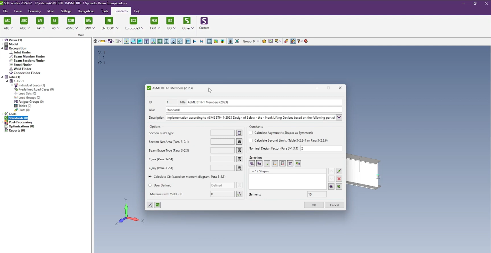
To incorporate the ASME BTH-1 (2023) standard into SDC Verifier, engineers can either access the standard through the main ribbon or right-click the “Standards” section in the project tree. From there, the standard can be selected and added to the model. Once added, the software automatically populates the structural checks based on the FEA model inputs, such as material properties and geometry.
Within SDC Verifier, the standard is structured to provide an organized framework for performing member checks. The checks are divided into property checks and load-related checks, ensuring that both the geometry and applied forces are accounted for. Each check is clearly labeled and can be individually accessed for further refinement or review.
Custom Settings for ASME BTH-1
When applying the ASME BTH-1 standard, specific settings must be configured to match the design requirements:
-
Section Build Type: The engineer must define whether the beam section is rolled or built-up.
-
C_LTB (Lateral-Torsional Buckling Coefficient): This coefficient, critical for I-shape sections and channels, is calculated based on bracing conditions and unbraced length. SDC Verifier allows automatic calculation of C_LTB, but it can also be set manually if required by the design scenario.
-
C_mx and C_my: These coefficients apply to bending terms in the interaction equations about the x- and y-axes, respectively. They account for prismatic member behavior under applied moments and curvature. By default, SDC Verifier assigns a value of 1, but lower values can be used if justified by the analysis.
-
Cb (Moment Modification Coefficient): Engineers can opt to calculate Cb automatically based on the moment diagram or input a user-defined value. The calculation follows the method described in Paragraph 3-2.3 of the standard, which adjusts the allowable bending stress based on the moment distribution along the unbraced length.
Handling Asymmetric Shapes and Designs Beyond Table Limits
SDC Verifier also includes options for handling more complex geometries. Asymmetric shapes, which are typically more challenging to analyze due to uneven stress distribution, can be treated as symmetric in the software, with minimum width and thickness applied for conservative calculations. Additionally, for designs that exceed the slenderness or width-to-thickness limits specified in the standard, the Calculate Beyond Limits option allows for continued analysis by reducing yield strength or other key parameters to meet the design limits, rather than halting the calculation.
These customization options provide engineers with the flexibility needed to adapt the ASME BTH-1 checks to their specific project needs, ensuring accurate results even in non-standard or complex scenarios.
Manual Calculation vs. FEA: A Comparison
In structural design, manual calculations remain a fundamental tool for validating FEA results. While FEA offers significant advantages in speed and complexity handling, traditional hand calculations provide a clear understanding of critical parameters and act as a benchmark for verification.
Manual Calculations Overview
In this section, we outline the step-by-step manual calculations essential for verifying the design of a spreader beam, particularly focusing on compliance with the ASME BTH-1-2023 standard.
Compactness Check:
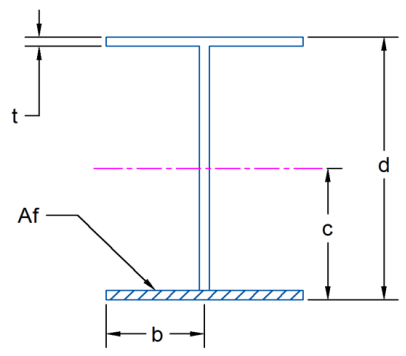
To begin, we assess whether the section is classified as compact according to Table 3-2.2-1. The flange slenderness λf\lambda_f is calculated as follows:
Next, we compare this value against the limit provided in Table 3-2.2.1:
Evaluating the condition: 5.79 < 10.25
This confirms that the flange is indeed compact.
Lateral Bracing Interval:
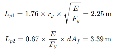
The next step involves checking the lateral bracing interval, which is derived from Equation (3-7):
Taking the minimum of these two values gives us:
To ensure compliance with Equation (3-6) for allowable bending stress, we conclude that the spacing of the gussets must not exceed 2.25 m.
Allowable Bending Stress Calculation:
Now we can compute the allowable bending stress as per Equation (3-6):
Load Considerations:
The load due to the lifted weight is calculated as:
Bending Moment Calculation:
The resulting bending moment M for the given load and beam length is determined by:
Bending Stress Computation:
Next, we compute the bending stress S using:
Utilization Factor:
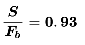
Finally, we calculate the utilization factor SF/b:
This analysis demonstrates that the spreader beam, utilizing an IPE600 section under the specified conditions, satisfies the requirements outlined in the BTH-1-2023 standard with an estimated utilization factor of 93% when lifting a 25-ton load.
FEA Results in SDC Verifier
In SDC Verifier, the same bending checks can be performed with greater efficiency. After setting up the model, including geometry, material properties, and loading conditions, the software automatically generates a comprehensive set of results for bending stresses and utilization factors.
-
Bending Checks: By navigating to the bending check section, engineers can either generate a table or plot the results. The extreme load case is selected, and the stress distribution is calculated throughout the beam, accounting for all load and boundary conditions.
-
Generating and Comparing Results: SDC Verifier allows engineers to produce detailed tables that show the bending stresses at critical points in the beam. These tables include values for both the calculated bending stress and the allowable bending stress based on the ASME BTH-1 standard.
-
Validation of Results: A crucial step in the process is comparing the FEA output with the manual calculations. In this case, the utilization factor derived from FEA matches the value obtained through manual calculation—both yielding a utilization of approximately 93%. This serves as a validation of the FEA model’s accuracy and ensures the structural integrity of the design.
By comparing manual calculations with FEA results, engineers gain confidence in the accuracy of their designs. Manual methods provide a transparent check, while FEA enables rapid analysis of complex geometries, loads, and conditions.
Interpretation of Results and Utilization Factor
The utilization factor is a key metric in structural analysis, representing the ratio of the applied stress to the allowable stress. It quantifies how much of the material’s capacity is being used under a given load condition. A utilization factor of 1 (or 100%) indicates that the structure is operating at its full capacity based on the design criteria, while values below 1 indicate a safety margin.
In this context, the utilization factor for the spreader beam is 0.93 (or 93%), meaning 93% of the allowable bending stress is utilized when lifting a 25-ton load. This factor provides insight into the structural performance—showing that the beam is safely within its design limits, but also close enough to maximize material efficiency without overdesigning.
Understanding the Data from SDC Verifier
SDC Verifier simplifies the process of calculating and interpreting stress distribution across a structure. The software compares the bending stress calculated from the finite element analysis (FEA) with the allowable stress as defined by ASME BTH-1 (2023). In this example, the FEA results show a calculated bending stress of 93.71 MPa, which is compared against the allowable stress of 100.83 MPa. This results in the previously mentioned utilization factor of 0.93.
SDC Verifier’s ability to automate the stress comparison process ensures accuracy and efficiency, especially in complex calculations where manual checks would be more time-consuming. The software not only provides stress values but also generates utilization factors, helping engineers quickly assess whether their design meets code requirements. This streamlined approach is critical when designing for safety and efficiency, as it ensures that critical limits are respected without unnecessary conservatism.
Future Enhancements and Conclusion
SDC Verifier is continuously evolving to meet the growing demands of structural analysis. Among the planned enhancements are additional checks for welds, bolts, and fatigue in lifting devices. These features will expand the range of compliance checks engineers can perform directly within the software, allowing for a more comprehensive evaluation of structural integrity beyond basic member checks. With these updates, engineers will be equipped to handle more complex design scenarios, ensuring adherence to critical safety standards across various loading conditions and structural components.
Conclusion
SDC Verifier’s integration of the ASME BTH-1 (2023) standard provides engineers with an efficient and precise solution for conducting member checks. The software’s automation of complex calculations, such as bending stress, utilization factors, and structural checks, enhances workflow and minimizes potential errors in manual calculations. With its user-friendly interface and advanced feature set, SDC Verifier enables engineers to confidently meet code requirements while optimizing structural performance.


 Key Parameters