The Achilles’ Heel of Crane Performance: Why Traditional FEA Models Fall Short in Stiffness Prediction

Have you ever wondered why precise crane stiffness prediction is crucial for safe and efficient operations? This article examines into the limitations of traditional FEA (Finite Element Analysis) models that rely on beam elements. We’ll expose how these models can miss critical details and potentially lead to inaccurate stiffness predictions.
Crane stiffness plays a paramount role in ensuring the smooth, safe, and efficient operation of these critical machines. A stiff crane exhibits minimal deflection under load, enabling precise positioning of cargo and mitigating potentially hazardous swaying during operation. Conversely, insufficient crane stiffness translates to excessive deflection, compromising control accuracy and introducing safety concerns.
Traditional finite element analysis (FEA) models often rely on beam elements to represent the crane structure. While computationally efficient, this approach suffers from a significant limitation: its inability to accurately capture the complexities of real-world crane geometries. Beam elements are essentially one-dimensional representations, neglecting the intricate details of features like:
- Welded connections: These junctions, where multiple structural members converge, introduce complex geometries that significantly influence how forces are transferred and impact overall stiffness. Beam elements struggle to represent these intricacies.
- Bolted connections: Similar to welded connections, bolted joints introduce geometric complexities that traditional FEA models often fail to capture accurately.
- Pinned connections: The way loads are transferred through pinned connections can have a substantial impact on crane stiffness. Beam elements may not adequately account for these specific load paths.
- Corners and sharp transitions: These features, often present around welded or bolted connections, can significantly affect the local stress distribution and influence overall stiffness. Beam elements struggle to represent these sharp geometric changes.
- Gantry systems: The gantry, the supporting structure that carries the hoisting mechanism, is a critical component often misrepresented by beam elements. Its complex geometry, involving multiple interconnected members, significantly impacts the crane’s overall stiffness.
These limitations of traditional FEA models using beam elements can lead to overestimated stiffness predictions. This overestimation translates to a false sense of security during operation, potentially masking potential safety hazards and compromising operational efficiency due to unforeseen excessive sway.
In the following sections, we’ll explore a more refined approach to crane stiffness prediction that addresses these shortcomings and ensures a more accurate representation of real-world crane behavior.
A Refined Approach to Crane Stiffness Prediction
Traditional FEA with beam elements provides a basic understanding of crane stiffness, but for more accurate predictions, a more refined approach is necessary. At SDC Verifier, we advocate for a hybrid modeling approach, our software leverages the strengths of both beam elements and detailed plate models.
This approach strategically combines:
-
Beam elements: These remain the foundation for modeling the overall crane structure due to their computational efficiency. They are well-suited for representing long, slender members like crane booms and legs.
-
Detailed plate models: These are incorporated in critical areas where complex geometries significantly influence stiffness. Plate elements are two-dimensional representations that offer a more accurate portrayal of these features.
1. Welded Connections:
- Beam element representation: A single beam element often connects multiple structural members at a weld, neglecting the intricate details of the weld geometry and the way load is transferred.
- Detailed plate model: This approach utilizes individual plates to represent the weld zone, capturing the interaction between the connected members and providing a more accurate representation of the stress distribution.
2. Bolted Connections:
- Beam element representation: Similar to welded connections, beam elements often simplify bolted joints, neglecting the influence of bolt holes and the surrounding material.
- Detailed plate model: This approach incorporates individual plates to represent the bolted connection, including the bolt holes and surrounding material. This allows for a more accurate analysis of stress concentrations and their impact on stiffness.
3. Pinned Connections:
- Beam element representation: Beam elements may not adequately capture the specific load path through a pinned connection, potentially leading to inaccuracies in stiffness prediction.
- Detailed plate model: This approach utilizes plate elements to model the specific geometry of the pin and its interaction with surrounding components, providing a more accurate representation of the load transfer mechanism and its influence on stiffness.
4. Corners and Sharp Transitions:
- Beam element representation: Beam elements struggle to represent the sharp geometric changes of corners and transitions, potentially leading to inaccuracies in stress distribution and stiffness prediction.
- Detailed plate model: This approach utilizes refined meshes with smaller elements to accurately capture the sharp geometries of corners and transitions. This allows for a more precise analysis of localized stresses and their impact on overall stiffness.
5. Gantry Systems:
- Beam element representation: Representing the complex geometry of the gantry system with beam elements often leads to significant underestimation of its influence on overall stiffness.
- Detailed plate model: This approach utilizes individual plates to model the various components of the gantry system, including columns, beams, and bracing members. This allows for a more accurate representation of the load path through the gantry and its contribution to the crane’s overall stiffness.
By incorporating detailed plate models in these critical areas, the hybrid modeling approach provides a more accurate representation of the crane’s actual geometry and behavior. This leads to significantly improved stiffness predictions compared to traditional beam element models.
The Advantages of Detailed Crane Modeling
The benefits of SDC Verifier’s hybrid modeling approach extend far beyond just achieving more accurate stiffness predictions. By incorporating detailed plate models in critical areas, we gain valuable insights that contribute to:
1. Improved Fatigue Life Assessment
Detailed stress analysis of welded connections becomes possible with the use of plate models. This allows us to identify locations where stress concentrations are most likely to occur. These areas are particularly susceptible to fatigue crack initiation and propagation over time. By pinpointing these critical zones, we can:
- Recommend targeted inspections and preventative maintenance strategies to mitigate fatigue risks.
- Implement weld design improvements to optimize stress distribution and extend the operational life of the crane.
2. Identification of Local Stress Concentrations
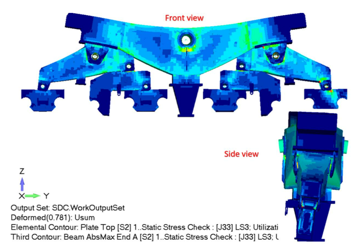
Detailed modeling provides a finer view of stress distribution throughout the crane structure. This allows us to identify areas where local stress concentrations occur, exceeding the material’s yield strength. These concentrations can lead to potential failures if left unaddressed. Early detection through detailed modeling enables:
- Implementing design modifications to redistribute stress and prevent localized failures.
- Optimizing material selection for specific locations based on the identified stress levels.
3. Enhanced Overall Structural Integrity Evaluation
The ability to accurately capture the behavior of critical connections and the gantry system through detailed modeling provides a more holistic understanding of the crane’s structural integrity. This allows for:
- A more comprehensive evaluation of the crane’s capacity to handle design loads and operational stresses.
- Identification of potential weak points in the structure before they become critical issues.
- Confidence in the crane’s ability to meet safety standards and regulations.
Impact on Design Optimization and Safety
The insights gained from detailed modeling contribute directly to optimized crane design. By understanding the true behavior of the structure under load, engineers can:
- Refine designs to achieve efficient load distribution and minimize stress concentrations.
- Select appropriate materials based on the actual stress levels experienced in critical areas.
Ultimately, detailed crane modeling fosters a proactive approach to safety. By identifying potential issues before they escalate, we can ensure the structural integrity of the crane, minimizing the risk of accidents and promoting safe and reliable operations.
Real-World Validation: Optimizing STS Crane with Detailed Modeling
A great example that showcases the effectiveness of our detailed modeling approach is the project we conducted together with Kalmar Netherlands on the comprehensive verification of the STS crane for the Euromax Terminal.
Due to modifications made to the crane to increase operational efficiency, a minimum natural frequency requirement was established.
Among other calculations such as strength, remaining lifetime, buckling, welds, bolts, lifting, transportations, etc., a stiffness study was also performed based on the finite element analysis method.
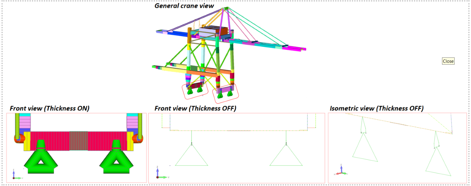
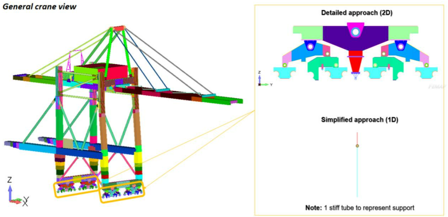
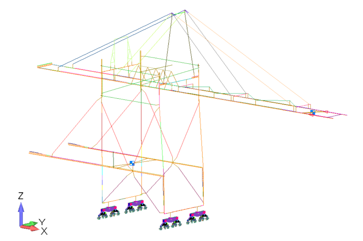
To demonstrate the critical role of detailed modeling of the gantry system in assessing crane stiffness, a series of normal modes analyses were conducted employing various modeling techniques and compared with the actual measurements.
Specifically, the gantry system was modelled using:
- 1D beam elements, a popular method within the engineering community
- detailed modelling approach with 2D elements (exact copy)
- detailed modelling approach with 2D elements of the similar gantry system (comparable design, but not identical)
Table with the results
|
Natural frequencies |
Beam Model. Case 1 |
Detailed FEA Model (similar design). Case 2 |
Detailed FEA Model (exact copy). Case 3 |
Actual Measurement. Case 4 |
Discrepancy (Case 1 / Case 2) |
Discrepancy (Case 1 / Case 3) |
Discrepancy (Case 2 / Case 3)
|
Discrepancy (Case 3 / Case 4)
|
|
Trolley Ride Direction |
0.895 |
0.603 |
0.690 |
0.691 |
32.63 % |
22.91% |
12.61% |
0.14% |
Based on the received FEA results and real measurements of the natural frequencies (see table above), several key findings were revealed:
- Accurate modeling of the gantry system is crucial for correct stiffness results, as shown by a very small discrepancy of 0.14% between the FEA results and actual measurements.
- Modeling the gantry system with simple beam elements can result in overestimated natural frequencies by over 32% compared to more detailed plate modelling approach
- Even detailed modeling based on similar cranes or configurations proved insufficient, showing over 12% discrepancy.
- The most accurate results require a detailed model that exactly matches the gantry system being used.
This reinforces the notion that traditional beam elements struggle to accurately capture the influence of the gantry’s geometry on overall stiffness.
In essence, this case study serves as a strong testament to our detailed modeling approach’s effectiveness. By focusing on critical areas like various connections and particularly the gantry system, the crane stiffness and natural frequencies can be predicted much more accurately, ensuring better design and safety.
Understanding the Achilles’ Heel: The Gantry System
Beam elements provide a basic understanding of gantry stiffness but miss important aspects like axial stiffness.
They overestimate stiffness by not accounting for the bending of individual gantry components. Additionally, these models struggle to capture torsional effects, leading to inaccurate predictions of the gantry’s ability to resist lateral forces.
In essence, the gantry system behaves more like a complex lattice than a simple beam. By incorporating detailed plate models for the gantry, we can account for the bending and torsion of individual components, providing a far more accurate representation of its actual stiffness characteristics. This allows us to predict the crane’s overall behavior with greater accuracy and avoid potential operational issues down the line.
Optimizing the Modeling Approach: Balancing Accuracy and Efficiency
Our targeted approach focuses on detailed modeling for the critical gantry system, achieving significant accuracy improvements while optimizing efficiency. This ensures cranes meet operational demands, fostering safety, efficiency, and a smooth workflow.
While detailed plate modeling of the entire structure would provide the absolute highest level of accuracy, it’s important to strike a balance between precision and practicality, often limiting it to the locally important connections modelled with plates. The good news for those who don’t want to model many areas in detail is that our case study has shown significant improvement can be achieved with a limited approach. Here’s how we optimize the modeling process:
Focus on the Gantry System: As we’ve seen, the gantry system is the primary culprit behind discrepancies in traditional beam element models. By prioritizing a detailed plate model for the gantry within the FEA analysis, we can significantly reduce the mismatch between predicted and measured natural frequencies making it almost identical. This targeted approach allows us to capture the complex behavior of the gantry, including bending and torsion effects, leading to a more realistic representation of the crane’s overall stiffness.
Conclusion
this exploration has highlighted the critical role of accurate crane stiffness prediction for ensuring operational safety, efficiency, and longevity. Traditional FEA models using beam elements, while computationally efficient, often fall short due to their inability to capture the complexities of real-world crane geometries.
SDC Verifier’s hybrid modeling approach bridges this gap. By strategically combining beam elements for overall structure modeling and detailed plate models for critical areas like welded connections, bolted connections, corners, and the gantry system, we achieve a significantly more accurate representation of the crane’s behavior.
The benefits extend beyond just improved stiffness predictions. Detailed modeling allows for:
- Enhanced fatigue life assessment through stress analysis of welds.
- Identification of local stress concentrations for preventative maintenance.
- Comprehensive evaluation of overall structural integrity.
This translates to:
- Optimized crane design with efficient load distribution and minimized stress concentrations.
- Enhanced operational efficiency through minimized sway and smoother cargo handling.
- Confidence in meeting safety standards and regulations.
The Kalmar Netherlands case study serves as a powerful testament to the effectiveness of our approach. Detailed modeling of the gantry system yielded a natural frequency prediction with a mere 0.14% discrepancy from actual measurements, compared to a significant overestimation using beam elements.


