


For civil engineering and many other industries, it is important to ensure that a structure meets the functional requirements – the Serviceability limit state (SLS). It does not involve collapse or strength of a building but impair it usefulness and stiffness.
What is a beam deflection check
The beam deflection is one of the checks that should be performed for serviceability limit state design. Deflection is the displacement within a structural member under the influence of loads, ignoring the displacements of the rest of the structure.
There are generally a few main components which make a crucial influence on the magnitude of beam deflection:
- Beam member span (unsupported length of the beam member);
- Magnitude of the applied load to the beam;
- Moment of Inertia, which depends on the cross-section size of the supported beam;
- Young’s Modulus, which depends on the material type of the supported beam;
Besides, type of the beam supports (constraints at the ends of the beam) determines the load transferring over the beam member (i.e. bending moment) and afterwards the maximum deflection of beam.
In engineering, the supported beams are classified into several main types, depending on their supports:
Simply supported beam
Simply supported beams have 2 supports, which are free to rotate and have no moment resistance – pinned and roller.

Fixed beam (at both ends)
Unlike simply supported beams, fixed beams have fixed supports, which are restrained from rotation – it provides the resistance moment at both ends.

Cantilever beam
Cantilever beams are supported at one end with a fixed support (same as fixed beams, but only with 1 support).

Continuous beam
Continuous beams are multi-span beams, which have more than 2 supports (e.g. one / several more supports are added along the simply supported beam).

Overhanging / double overhanging beam
Overhanging / double overhanging beams are the simple beams, which have one / two ends extending beyond their supports accordingly (e.g. simply supported beam, which have one / two free ends).

All these supported beam members will get the different maximum deflection under the same loading, e.g. self-weight, which can be applied as a uniform distributed load.
Example:
Supported beam members on the pictures below, which have the same parameters of material type (Young’s Modulus), properties of cross-section and length, are subjected to the same value of a uniform distributed load.
Note: A distributed load is applied along the full length of the beam members.


There are plenty of formulas and beam deflection equations can be found to determine the maximum beam deflection by hand calculation, although they all will lead to the approximately same outcome.
As can be seen on the picture above, a uniform distributed load results in the different values of maximum deflection (\[\delta_{max}\]), depending on the beam type (supports).
The cantilever beams deflect more than other beam members because of support only at one end (in case of overhanging beam, the maximum deflection is bigger under the same distributed load compared to cantilever beam, because of allowed rotation for the free end, which has the same beam length).
The lowest max. beam deflection over the all beam members is found in the fixed beam. Due to the uniform distributed load, which is applied along the full beam length, it appears in the middle of span in the same way as in case of simply supported beam.
Note: A distributed load applied to the beam results in a smoother deformation in this area compared to the point loads – and therefore smoother beam deflection. Distributed load is applied along the full length of the beam members.
You can now see how many factors should be taken into account in the appropriate beam deflection equations to solve these simple examples.
However, the real structures normally include a lot of different beams and loads, that this task becomes complex and requires quite a lot of time for the hand calculation, which is the reason of automation of all formulas (including deflection equations) in the CAE software we use nowadays.
How to calculate beam deflection in a FEM model
A general CAE package (like Ansys, Femap, Simcenter3D, etc.) makes an engineering life much easier, although still remains a time-consuming task for performing a beam deflection check because:
- Beam member deflection is not the same as the nodal displacement of the beam member nodes
- Deflection limit depends on the type of beam member and the beam member span (member length)
- The beam deflection needs to be checked for every load scenario (sometimes it can be hundreds / thousands load situations)
Difference between model displacement and beam member deflection
The first problem is that a finite element analysis does not provide you directly beam deflection results but only nodal displacements in the global coordinate system, which requires additional post-processing. The influence of the displacement of the support points of the beam member should be removed from the displacement of the nodes of the beam member.

What is the allowable beam deflection?
The beam deflection limits vary between standards and can be even different for different countries what share the same standard as the Eurocode series where each country can further specify limits in national annexes.
In general the deflection limits are based on beam members lengths (span) which results in different allowable deflections in every point or node of the construction. For example the serviceability limits suggested by the UK National Annex for the Eurocode 3 (BS EN 1993-1-1) for allowable vertical and horizontal deflections are shown below:
| Cantilevers | Length/180 |
| Beams carrying plaster of brittle finish | Span/360 |
| Other beams (except purlins and sheeting rails) | Span/200 |
| Purlins and sheeting rails | To suit the characteristics of particular cladding |
It means, that these deflection equations need to be transferred to all beam member nodes in the model:

Load combinations
Because standards prescribe to check large number of load scenarios (or load cases as we call them in SDC Verifier) the beam deflection check needs to be repeated also for all these load cases.
Note: In the example at the beginning of the article only the 1 distributed load is shown, while usually there are a lot of others loads to be combined.
For simple analysis (e.g. 50 beam members and 20 load scenarios) an engineer should perform 50 x 20 = 1000 calculations. Consider how much time you need for complex models with more than a hundred load cases and much more beam members.
SDC Verifier solution for beam deflection check
How to calculate deflection of a beam in the quickest and most convenient way? These difficulties above have forced us to automate all these calculation steps in SDC Verifier software.
Beam member recognition
With a help of Beam Member Finder tool SDC Verifier automatically recognizes beam member lengths:

Recalculation of nodal calculation to beam member deflection
All the required deflection equations are implemented into the software to make the deflection of all the nodes of the beam member calculated automatically. For all individual loads and all load combinations the global deformation of the beam member nodes and the support nodes are transferred into beam member deflection results. The maximum deflection of the nodes of a member is compared by the specific deflection limit. The picture below shows for single load case both the total global displacements (left) and the beam member deflection (right)

For beam member 7 the deflection for load combination one is shown below:

Load group results (envelope results)
To evaluate if the deflections are below the limits, it’s enough to display one table or plot for a group of load scenarios or Load Group in SDC Verifier.
The table below summarizes the results and indicates which load scenario is governing (the source of the absolute maximum deflection) for each beam member:
| Member | Length | Min Deflection | Max Deflection | Deflection / Length | Allowable | Utilization Factor | Source Load |
|---|---|---|---|---|---|---|---|
| Member 1 | 3000 | -1.11 | 1.11 | 0.000370 | 0.005 | 0.07 | LC4 |
| Member 2 | 3000 | -1.11 | 1.11 | 0.000370 | 0.005 | 0.07 | LC4 |
| Member 3 | 3000 | -0.55 | 0.55 | 0.000182 | 0.005 | 0.04 | LC4 |
| Member 4 | 3000 | -0.55 | 0.55 | 0.000182 | 0.005 | 0.04 | LC4 |
| Member 5 | 4000 | 0.0 | 0.71 | 0.000178 | 0.005 | 0.04 | LC2 |
| Member 6 | 4000 | 0.0 | 0.71 | 0.000178 | 0.005 | 0.04 | LC2 |
| Member 7 | 4000 | -4.82 | 0.0 | 0.001200 | 0.005 | 0.24 | LC2 |
| Member 8 | 4000 | -4.82 | 0.0 | 0.001200 | 0.005 | 0.24 | LC2 |
| Submember 9.1 | 3000 | 0.0 | 0.8 | 0.000266 | 0.005 | 0.05 | LC4 |
| Submember 9.2 | 3000 | 0.0 | 1.66 | 0.000554 | 0.005 | 0.11 | LC4 |
| Submember 10.1 | 3000 | 0.0 | 1.66 | 0.000554 | 0.005 | 0.11 | LC4 |
| Submember 10.2 | 3000 | 0.0 | 0.8 | 0.000266 | 0.005 | 0.05 | LC4 |
| Submember 11.1 | 3000 | 0.0 | 1.66 | 0.000554 | 0.005 | 0.11 | LC4 |
| Submember 11.2 | 3000 | 0.0 | 0.8 | 0.000266 | 0.005 | 0.05 | LC4 |
| Submember 12.1 | 3000 | 0.0 | 0.8 | 0.000266 | 0.005 | 0.05 | LC4 |
| Submember 12.2 | 3000 | 0.0 | 1.66 | 0.000554 | 0.005 | 0.11 | LC4 |
| Member 13 (Y) | 5000 | 0.0 | 0.0 | 0.000000 | 0.005 | 0.0 | LC1 |
| Member 14 (Y) | 5000 | 0.0 | 0.0 | 0.000000 | 0.005 | 0.0 | LC1 |
| Member 15 (Y) | 5000 | 0.0 | 0.0 | 0.000000 | 0.005 | 0.0 | LC1 |
| Member 16 (Y) | 5000 | 0.0 | 0.0 | 0.000000 | 0.005 | 0.0 | LC1 |
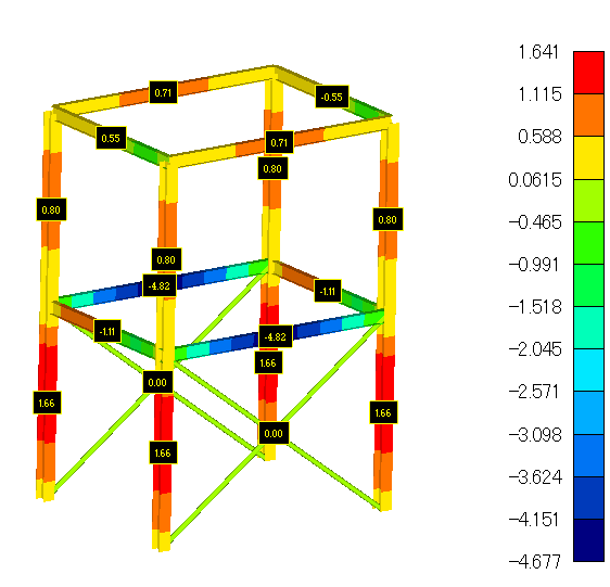
The extreme results of deflection of beam calculation (min/max/absmax) can be shown over the all load combinations in one picture!
On the example below, we show the maximum beam deflection results for the full model and all load scenarios:
Conclusion
SDC Verifier contains all the necessary tools to perform the deflection check quickly directly within your favorite Finite Element Analysis (FEA) software. (Ansys, Femap and Simcenter 3D are currently supported). The automatic beam member recognition, result transformation and the usage of the envelope results of a load group reduce the calculation and post processing time significantly. So if you are looking for a tool to check the results of your model directly within your FEA software, SDC Verifier offers you all the tools to quickly comply with Standards without tedious manual post-processing.


