Mobile Elevating Work Platforms (MEWPs): The Ultimate Guide to Engineering Compliance with EN 280


This comprehensive guide is designed to demystify the technical complexities of EN 280 for engineers and business owners alike. Whether you’re an engineer tasked with designing robust MEWP structures or a business owner seeking to understand the safety implications of this standard, this resource will equip you with the knowledge to make informed decisions.
What is the EN 280 standard?
EN 280 is the European standard that sets the definitive safety requirements for Mobile Elevating Work Platforms (MEWPs). These versatile machines, used across industries like construction, maintenance, and entertainment, elevate personnel to working positions. EN 280 covers a wide range of MEWPs, from scissor lifts and boom lifts to vehicle-mounted and self-propelled platforms. The standard’s scope encompasses design calculations, stability criteria, construction, safety features, examinations, and tests, ensuring a holistic approach to MEWP safety.
Legal and Business Imperatives
Compliance with EN 280 is not merely a recommendation; it’s a legal obligation for manufacturers, owners, and operators in Europe. Non-compliance can lead to severe consequences, including:
- Legal Penalties: Fines, legal action, and potential criminal charges.
- Financial Losses: Increased insurance premiums, equipment downtime, and project delays.
- Reputational Damage: Loss of trust from clients, partners, and the public, potentially leading to reduced business opportunities.
Conversely, adhering to EN 280 offers a multitude of benefits:
- Safety: Reduced risk of accidents, injuries, and fatalities.
- Risk Mitigation: Minimized liability exposure and legal complications.
- Operational Efficiency: Improved productivity, reduced downtime, and increased equipment lifespan.
- Competitive Advantage: Demonstrated commitment to safety, attracting more clients and projects.
Modeling and Simulation
The initial phase of engineering analysis involves the creation of global models. These simplified models, often constructed using beam elements, serve as a foundational representation of the structure.
While they do not capture the full complexity of the machine, global models are instrumental in identifying critical load points, defining the operational conditions, and understanding the overall load distribution.
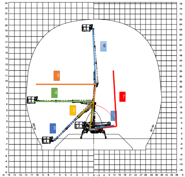
Global models are typically created using beam elements that approximate the actual shape and mass distribution of the MEWP structure. To ensure structural integrity under various operational conditions, static structural calculations are employed to simulate the MEWP’s behavior in several operational positions to define worst-case scenarios.
Figure: MEWP Global Model with Seven Operational Positions Highlighted
These positions are carefully selected to identify scenarios where the MEWP is subjected to the highest stresses and loads.
Detailed Modeling
After gaining initial insights from a simplified global model, typically constructed using beam elements, engineers employ Finite Element Analysis (FEA) to create a more nuanced representation of the structure. This detailed FEA model comprises a network of smaller, interconnected elements, enabling a highly localized examination of stresses, strains, and deformations within the MEWP under various load conditions.
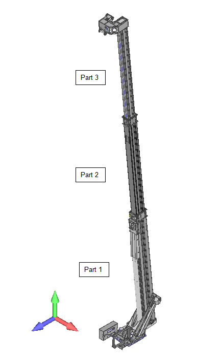
Figure 2: Detailed FEA Model of a MEWP with Three Boom Parts (Part 1, Part 2, Part 3) Highlighted
In the case of MEWPs, detailed models often focus on the boom sections and connections, as they are subject to significant bending and compressive forces. As shown in Figure 2, the boom is divided into three distinct parts (Part 1, Part 2, and Part 3), each of which can be analyzed separately using FEA to understand its specific structural behavior. The loads derived from the global model for each operational position are then transferred to these detailed models to assess the stress distribution and ensure structural integrity under various conditions.
By applying various load scenarios, including those derived from EN 280, engineers can assess the structural response with a high degree of accuracy.
Worst-Case Scenarios
A crucial aspect of MEWP engineering involves identifying and modeling worst-case operational scenarios. These scenarios encompass combinations of maximum loads, extreme angles, and unfavorable operating conditions.
Load Calculations
EN 280 provides a framework for evaluating the various forces acting on a MEWP during its operation, ensuring it can withstand these loads without compromising structural integrity.
Individual Loads
The assessment begins by analyzing individual loads, each representing a specific force, pressure, acceleration, or displacement acting on the MEWP:
- Rated Load. This is the maximum intended load designed to carry, including the weight of occupants, tools, and materials on the platform. Bucket barrier loads are also considered for MEWPs with this feature.
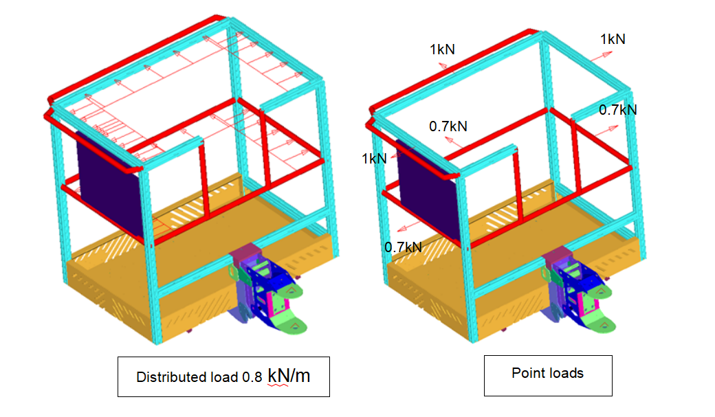
Figure 3: Depiction of Bucket Barrier Loads on a MEWP
As shown in Figure X, these loads typically include a distributed load applied horizontally to both the top and bottom rails of the barrier (0.8 kN/m in this example) as well as point loads applied to the middle of these rails (1 kN on the top rail and 0.7 kN on the bottom rail). These loads simulate the forces that the barrier would experience during operation, such as from the weight of tools or materials placed in the bucket or from accidental impact.
- Wind Loads. Wind forces can significantly affect MEWP stability. EN 280 and ISO 4302 provide guidelines for calculating wind loads based on wind pressure, shape factors (accounting for the aerodynamic properties of the MEWP), and the projected area of the machine.
EN 280 mandates that MEWPs intended for outdoor use be designed to withstand a wind pressure of 100 N/m^2, equivalent to a wind speed of 12.5 m/s (Beaufort Scale 6). This standard wind load is applied horizontally to the center of area of the MEWP and its occupants, simulating the worst-case scenario.
To account for the varying shapes and sizes of MEWP components, EN 280 introduces shape factors. These factors adjust the wind load based on the geometry of the exposed surface, ensuring a more accurate assessment of wind forces. For instance, L-, U-, T-, and I-sections have a shape factor of 1.6, while circular sections have factors ranging from 0.8 to 1.2, depending on their size.
- Manual Force. Operators exert force on the MEWP controls, and this force must be accounted for. EN 280 specifies a value of 400 N for manual force.
- Dynamic Loads. MEWPs experience dynamic loads due to acceleration and deceleration during movement.
EN 280 accounts for dynamic loads caused by acceleration, deceleration, and slewing by applying a factor of 0.1 to the forces created by structural masses and the rated load. This factor is applied in the direction of movement that creates the greatest overturning moment, ensuring that the MEWP remains stable during operation.
The table below illustrates an example of how dynamic loads are calculated for a MEWP:
Table: Example of Dynamic Load Calculation for MEWP Components
In this example, the dynamic load in the X and Y directions for the bucket and jib is equal to their respective masses multiplied by the acceleration due to gravity (9.81 m/s²). However, the dynamic load in the Z direction for the boom is only half of its mass multiplied by the acceleration due to gravity, reflecting the fact that the boom experiences less vertical acceleration compared to other components.
- Tilting. The MEWP’s ability to tilt due to uneven terrain or operator actions is a critical factor.
EN 280 addresses this by requiring stability calculations to be performed on the maximum allowable chassis inclination defined by the manufacturer, plus an additional 0.5 degrees for setup inaccuracy.
Stabilizers play a crucial role in maintaining stability on uneven terrain. EN 280 mandates that MEWPs equipped with stabilizers must be able to level the chassis or extending structure within the maximum allowable inclination.
Load Combinations
MEWPs rarely experience only one type of load at a time. Therefore, engineers create load combinations that simulate various operational and testing scenarios. These combinations consider the simultaneous application of multiple loads, such as rated load combined with wind load and dynamic loads.
Load Combinations and Factors as per EN 280
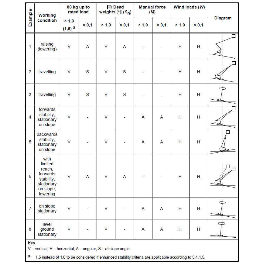
To assess the MEWP’s structural integrity and stability under realistic operating conditions, EN 280 prescribes specific load combinations and factors. These combinations consider the simultaneous application of multiple loads, such as the rated load, dead weights, manual force, and wind loads. The factors are applied to each load type to account for their varying significance and potential variability.
As illustrated in the table above, each working condition requires a unique combination of loads and factors. For example, during raising and lowering (condition 1), the rated load and dead weights are considered with a factor of 1.0, while wind loads are considered in both horizontal directions with a factor of 0.1.
EN 13001 Load Factors
To ensure safety, EN 13001 introduces partial safety factors. These factors are applied to each individual load to account for uncertainties in load estimation and material properties.
The resulting factored loads are used in structural calculations to determine if the MEWP design meets the required safety levels. For example, a typical load factor for the rated load might be 1.35, meaning the design must withstand 135% of the expected rated load.
Stability Analysis
Stability is paramount in MEWP operation, as the risk of tipping over poses a significant hazard to operators and those nearby. EN 280 mandates rigorous stability analysis to ensure MEWPs remain secure under various conditions.
Support Positions
The stability of a MEWP varies significantly depending on its leg configuration. When all four legs are fully extended (wide position), the machine can typically rotate a full 360°. However, in the “wide/narrow” configuration, rotation is often limited due to the asymmetrical base of support.
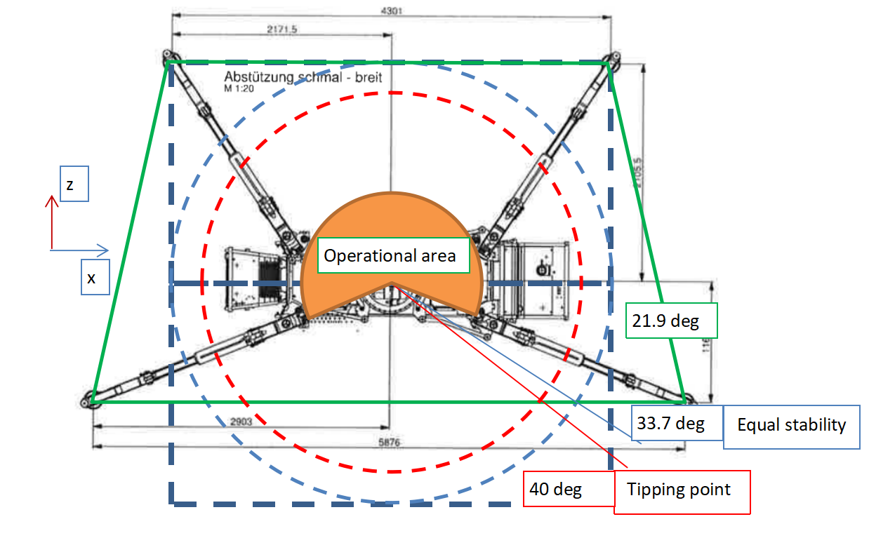
Stability diagram for a MEWP in a wide/narrow support position, illustrating operational boundaries, equal stability angles, and tipping points.
Figure above demonstrates how the operational area is restricted in the “wide/narrow” position compared to the full “wide” position. The diagram also indicates the critical “equal stability” angle, where the tipping moment is equal in both the forward and backward directions. Exceeding this angle in either direction increases the risk of tipping. The “tipping point” indicates the maximum angle before the MEWP becomes unstable and overturns.
Tipping Moment Calculations
A fundamental concept in stability analysis is the tipping moment. This is the moment (force multiplied by distance) that tends to cause the MEWP to tip over. Engineers calculate tipping moments for various load combinations and operational positions. By comparing these moments to the MEWP’s resisting moment (provided by its weight and leg configuration), they determine the margin of stability.
EN 280 sets minimum safety factors for tipping moments, ensuring that the MEWP’s resistance to tipping exceeds the applied moments by a substantial margin.
Velocity Considerations
MEWP movement introduces dynamic forces that can affect stability. EN 280 acknowledges this and sets limits on allowable velocities, particularly during rotations. Sudden movements or excessive speeds can shift the MEWP’s center of gravity, potentially leading to instability.
Engineers factor in dynamic loads resulting from acceleration and deceleration when calculating tipping moments. They also assess the MEWP’s control system, ensuring it can smoothly manage movements and prevent abrupt changes that could compromise stability.
Structural Design and Verification
To address the complexities of structural design and verification, EN 280 references EN 13001-3, a standard that provides detailed guidelines for the design of steel structures.
Material Properties
The choice of steel grades for MEWP components is critical. Common grades like S235, S275, and S355, each with distinct yield and ultimate tensile strengths, are often used. ‘
Engineers meticulously select materials based on their mechanical properties (yield strength, ultimate strength, elongation) and the specific load-bearing requirements of each component.
These material properties are then input into FEA models to accurately simulate the MEWP’s structural behavior.
Proof of Static Strength
Every welded joint, bolt connection, pin, and other critical component undergoes rigorous verification to confirm its static strength. This involves analyzing stresses under various load combinations, ensuring they remain below allowable limits.
Finite element analysis (FEA) is indispensable in this process, allowing engineers to visualize stress distributions with high precision and identify potential weak points in the structure.
Fatigue Analysis
MEWPs experience cyclic loading during operation, leading to fatigue. Fatigue analysis assesses the cumulative damage caused by these repeated loads.
FEA simulations can accurately predict stress concentrations and areas prone to fatigue failure. By understanding the fatigue life of critical components, engineers can recommend appropriate maintenance intervals and design modifications to extend the MEWP’s service life.
Buckling Analysis
Slender structural members and hydraulic cylinders are susceptible to buckling under compressive loads. Buckling analysis, often performed using FEA, determines the critical load at which these components would buckle and fail. Engineers incorporate appropriate safety factors to ensure that the MEWP’s design can resist buckling even under extreme conditions. FEA simulations are particularly valuable in buckling analysis, as they can model complex geometries and load scenarios with high accuracy.
Testing and Validation
The culmination of the MEWP design process involves rigorous testing and validation to ensure that the theoretical calculations and simulations align with real-world performance.
Test Loads
Testing encompasses a variety of scenarios, each designed to stress the MEWP and evaluate its structural integrity under different conditions:
- Overload Test. This test subjects the MEWP to loads exceeding its rated capacity (typically 125%) to assess its ability to handle unexpected overloads without failure.
- Stability Test. The stability test verifies that the MEWP remains stable under various load combinations, including those simulating wind forces and uneven terrain. This test typically involves tilting the MEWP to a predetermined angle and ensuring it does not tip over.
- Functional Test. This comprehensive test evaluates the overall functionality, including its control systems, safety devices, and emergency procedures. It confirms that the MEWP operates as intended and that all safety mechanisms function correctly.
Compliance with Standards
Testing serves as the final checkpoint for ensuring MEWP compliance with EN 280 standards. It bridges the gap between theoretical design and real-world operation, providing concrete evidence that the MEWP is safe and reliable.
Checklist for Engineers and Operators:
To ensure that all necessary tests and inspections are conducted, engineers and operators can use the following checklist:
|
Test/Inspection |
Initial Certification |
Ongoing Compliance |
Frequency (Minimum) |
|
Design Check |
✅ |
– |
– |
|
Manufacturing Check |
✅ |
– |
– |
|
Static Stability Test |
✅ |
– |
– |
|
Dynamic Stability Test (for types 2 and 3) |
✅ |
– |
– |
|
Overload Test |
✅ |
✅ |
As needed |
|
Functional Tests |
✅ |
✅ |
As needed |
|
Visual Examination |
– |
✅ |
Annually |
|
Brake Test |
– |
✅ |
Annually |
Conclusion
By adhering to these guidelines and leveraging finite element analysis, engineers can design MEWPs that not only meet regulatory requirements but also excel in performance, durability, and safety.
Business owners, on the other hand, must recognize that EN 280 compliance is not just a legal obligation but a strategic investment.
By embracing this standard and fostering a culture of safety, the MEWP industry can continue to reach new heights while safeguarding its most valuable asset: its people.
