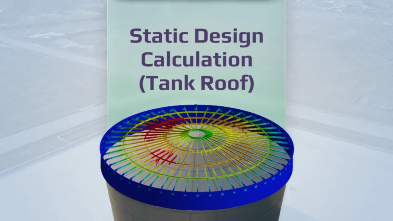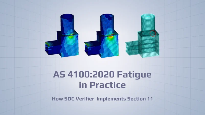
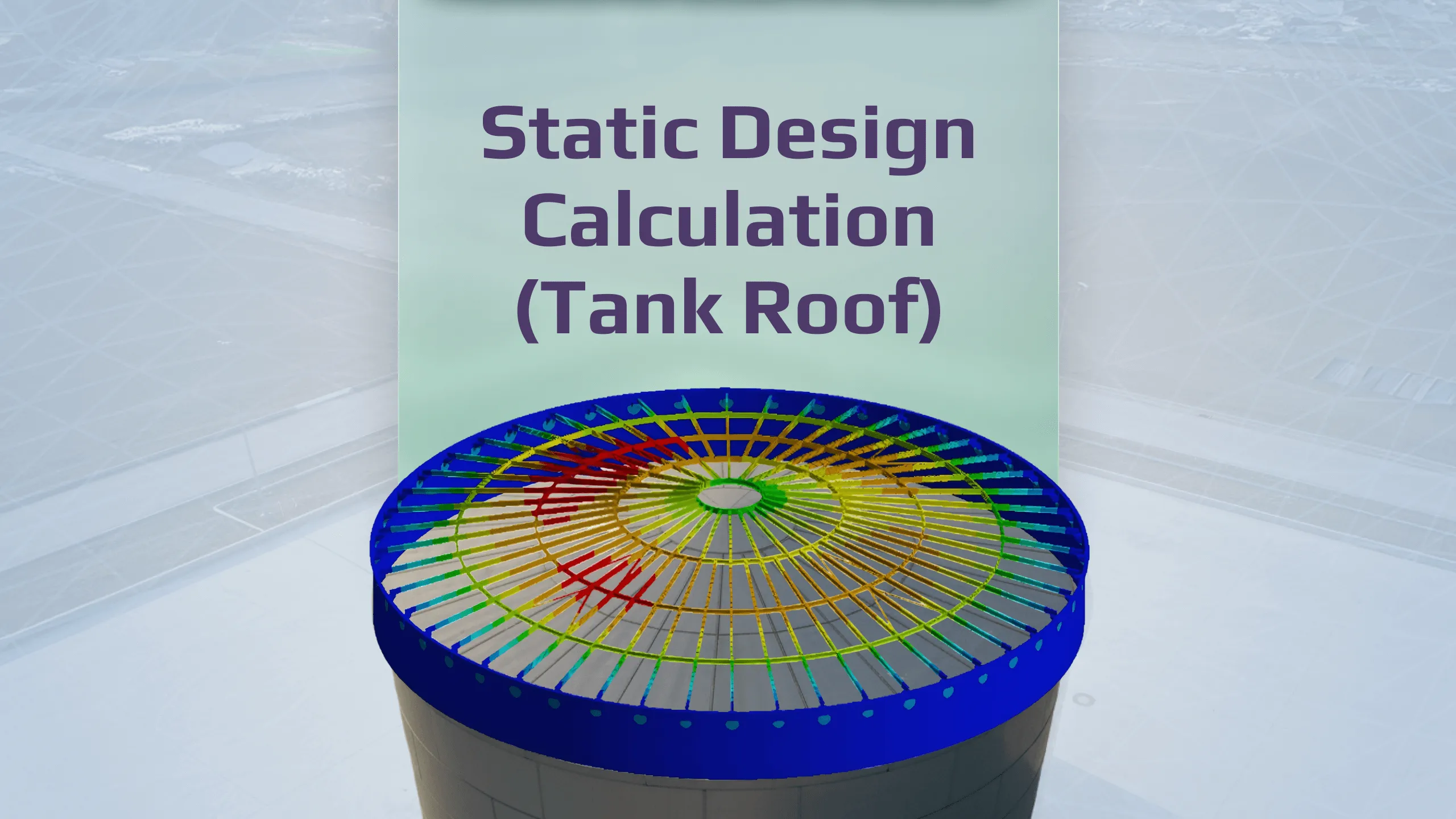
Verwater verified a 24 m storage-tank roof using SDC for Ansys
100%
ULS combinations passed (LS1–LS6)
100%
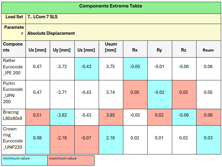
SLS combinations within limits (peak deflection 3.85 mm, LCom 7)
- Verwater built the model in Ansys and used SDC for Ansys for Eurocode checks and clause-referenced reporting.
- Combinations followed NEN-EN 1990/NB (ULS LS1–LS6; SLS LCom 7–10); EN 14015 was the project basis.
- ULS: Cross-Section Overall checks compliant. SLS: deflections within limits.
- Roof designed for modular fabrication, in-tank assembly, and bracket hoisting; temporary and final states checked.
Project at a Glance
- Asset: Atmospheric storage tank, Ø 24 m
- Scope: Replace top shell course + cone roof due to corrosion
- Role: Static design calculation + code checks + audit pack
- Fabrication: Modular sections, shop-made; in-tank assembly; hoisted onto brackets on new top shell course
- Standards: Design basis — EN 14015; Checks — NEN-EN 1990/NB (combinations), EN 1993-1-1/NB, EN 1993-1-8.
- Software: SDC for Ansys
- Outcome: ULS capacity acceptable; SLS deflections within limits; Eurocode checks passed; design aligned with EN 14015 project requirements.
The Challenge
Corrosion in the cone roof and top shell course required full replacement. Verwater handled the design and engineering. The design had to follow EN 14015 as the project basis and the relevant Eurocode provisions, with documentation suitable for audit. It also needed to be shop-fabricated in transportable modules and assembled inside the tank. Finally, the roof had to limit serviceability deflections and demonstrate adequate ultimate capacity.
Objectives & Constraints
Primary objective: Verify strength, stability, and serviceability of the new cone roof to EN 14015, NEN-EN 1990/NB, and EN 1993-1-1/-1-8.
Constraints
- Shop fabrication in transportable modules.
- In-tank assembly.
- Hoisting onto brackets on the new top shell course.
- Adherence to the project’s National Annex (NB) requirements.
Approach
1) Modeling & Pre-Processing
- Geometry built in Ansys SpaceClaim; FE model prepared for Ansys Mechanical 2024 R2.
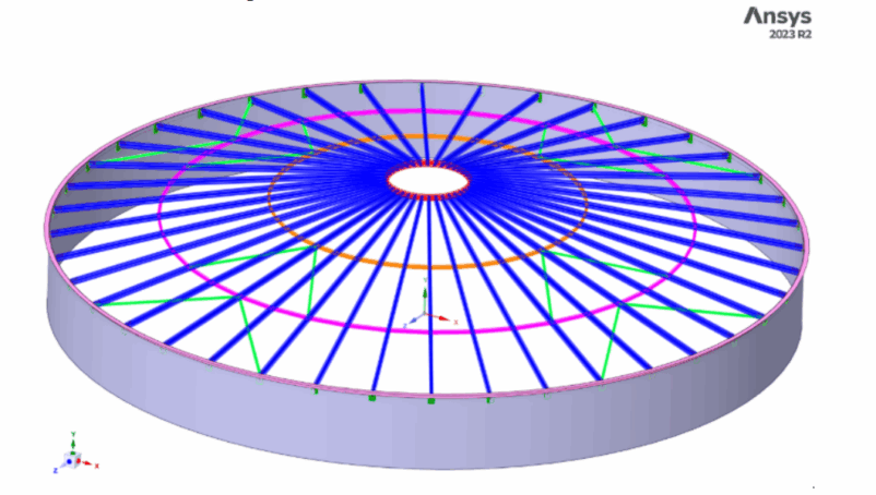
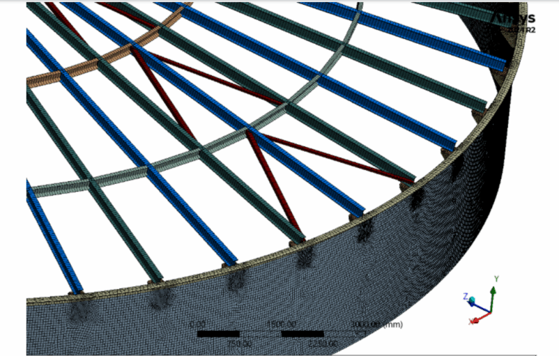
- Member catalog per design intent: Rafters IPE200, Purlins UNP200, Crown ring UNP220, Bracing L80×80×8.
Figure. SpaceClaim model: rafters, purlins, crown ring, and bracing.
- Materials and connections per project spec; welded connections checked to EN 1993-1-8.
Figure. Roof member arrangement with bracing.
2) Loads & Combinations
- Permanent actions (G) and variable actions (e.g., snow/wind/maintenance) per EN 14015 project basis.
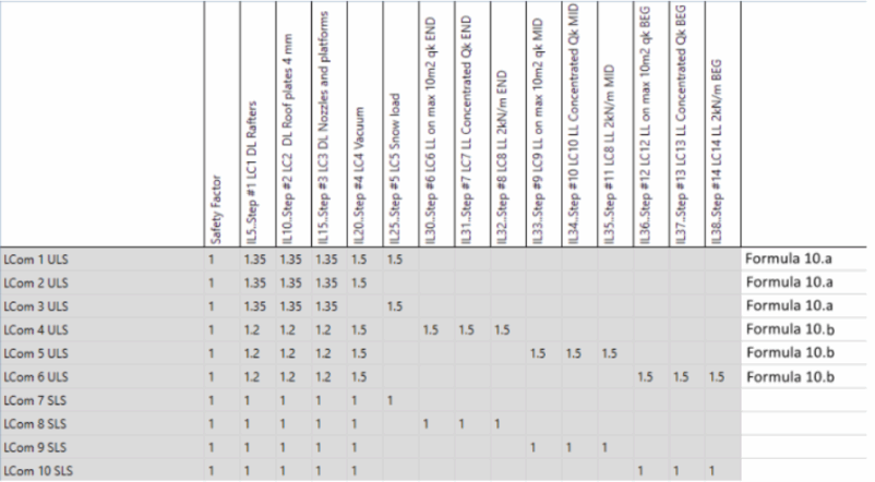
- Combinations per NEN-EN 1990/NB: ULS LS1–LS6, SLS LCom 7–LCom 10.
- Load set naming and factors documented for audit.
Load combination matrix per NEN-EN 1990/NB (Formulas 10a/10b
3) Analysis
- Global linear static analysis in Ansys Mechanical for internal forces and nodal displacements.
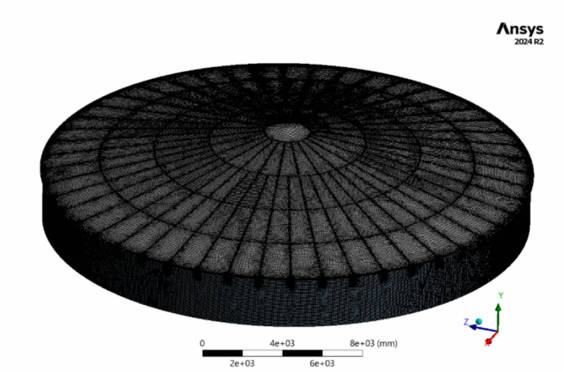
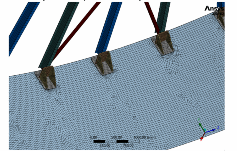
Figure. Global mesh of the tank roof model (Ansys Mechanical 2024 R2).
- Element types and mesh settings are included in the model files; forces and displacements from the final run were used for checks.
4) Code Checks & Post-Processing
SDC for Ansys used for automated code checks and combinations:
- EN 1993-1-1/NB member strength & stability (Cross-Section Overall).
- EN 1993-1-8 connection verifications as required.
- Serviceability deflections vs. project criteria.
Clause-referenced reporting via Report Designer (inputs, factors, utilization, references).
5) Verification
-
Results verified to NEN-EN 1990/NB and EN 1993-1-1/NB.
- Spot checks with Excel manual calculations for critical members.
Key Results
The model and displacements are from Ansys Mechanical. Load combinations, Eurocode checks, and the tables were set up and reported with SDC for Ansys. EN 14015 was the project basis; checks followed NEN-EN 1990/NB and EN 1993-1-1 (with EN 1993-1-8 where needed).
Serviceability (SLS)
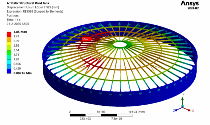
- Peak resultant displacement: ≈ 3.85 mm at Bracing L80×80×8 (LCom 7).
LS displacement (Usum) for LCom 7; peak ≈ 3.85 mm. Same load case as the Components Extreme Table below.
- Representative maxima (Usum): Rafters IPE200 ≈ 3.75 mm; Purlins UNP200 ≈ 3.74 mm; Crown ring UNP220 ≈ 2.16 mm.
- Values per local coordinate system; detailed tables are in the report.
Components Extreme Table for LCom 7 (SLS); values in local coordinate system.
Ultimate Limit State (ULS) — EN 1993-1-1/NB
- Cross Section Overall checks for LS1–LS6: compliant.
- Highest UfSection = 0.13 at Purlin UNP200 (LS1).
Table Cross Section Overall, calculated for load combination 1, ULS. Uf Section column shows the maximum calculated values over all columns.
ULS evidence (LS2–LS6)
Table Cross Section Overall, calculated for load combination 2, ULS. Uf Section column shows the maximum calculated values over all columns.
Table Cross Section Overall, calculated for load combination 3, ULS. Uf Section column shows the maximum calculated values over all columns.
Table Cross Section Overall, calculated for load combination 4, ULS. Uf Section column shows the maximum calculated values over all columns.
Table Cross Section Overall, calculated for load combination 5, ULS. Uf Section column shows the maximum calculated values over all columns.
Table Cross Section Overall, calculated for load combination 6, ULS. Uf Section column shows the maximum calculated values over all columns.
- Typical UfSection ranges (member maxima): Rafters IPE200: 0.03–0.09; Purlins UNP200: 0.10–0.13; Crown ring UNP220: 0.04–0.07.
Compliance Statement
- EN 14015 functional requirements met.
- ULS: strength and stability adequate per EN 1993-1-1/NB.
- SLS: deflections within project limits; combinations per NEN-EN 1990/NB.
Why SDC for Ansys Was Chosen for This Project
Verwater needed to run Eurocode checks inside Ansys and hand over an audit-ready report (EN 14015 as the project basis).
“We use Ansys SpaceClaim for 3D modeling and Ansys Mechanical for structural simulations. With SDC Verifier, we ensure our designs meet all required code checks and are optimized to withstand the applied loads. The software also enables us to generate all necessary load combinations in accordance with the applicable design codes for storage tanks.” — Ashraf Mir, FEM Engineer, Verwater
What this delivered
- On-model checks in Ansys — no re-exports, no macros.
- Clause-referenced reports — Eurocode (EN 1993) with combinations per NEN-EN 1990/NB; EN 14015 as project basis.
- Repeatable setup — same combination logic reused across variants/changes.
Fabrication and installation plan
- Roof segmented into transportable modules for shop fabrication.
Figure. Bracket support region prepared for checks.
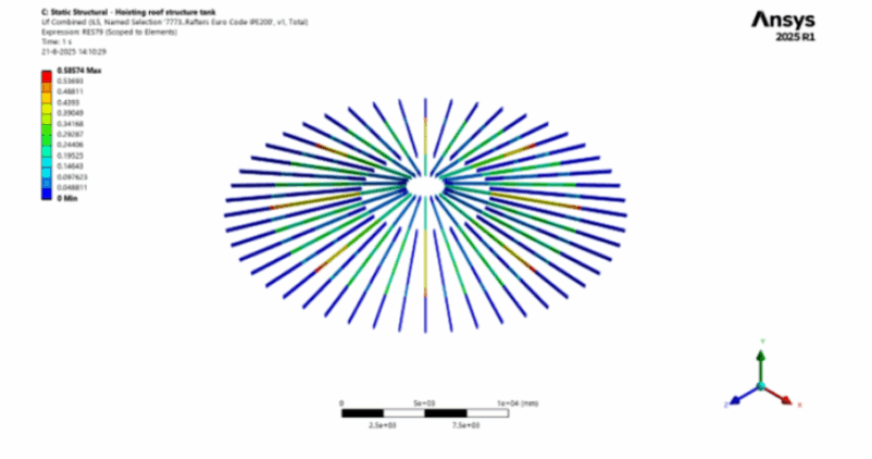
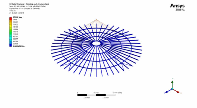
- In-tank assembly with bracket hoisting on the new top shell course; checks confirm temporary and final states are within code limits (where applicable).
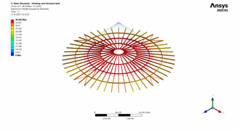
Figure: Displacement contour (Usum) for the hoisting condition.
Deliverables
- Clause-referenced SDC Verifier report (ULS/SLS, combinations, inputs, factors, member utilizations, figures).
- Model files (Ansys), check setup, and result envelopes.
- Calculation annex with Excel verification snippets for critical checks.
Wrap-up
Verwater designed and verified a new 24 m cone roof to replace the corroded roof and top shell course. The team modeled in Ansys SpaceClaim, ran the analysis in Ansys Mechanical 2024 R2, and used SDC for Ansys for Eurocode checks (EN 1993-1-1/-1-8 with combinations per NEN-EN 1990/NB). EN 14015 served as the project basis.
All ULS combinations (LS1–LS6) passed. SLS deflections were within limits, with a peak of 3.85 mm (LCom 7). The modular fabrication, in-tank assembly, and bracket hoisting were checked for temporary and final states.
Deliverables included a clause-referenced report, model files, and an Excel calculation annex—ready for audit and handover.
