Overcoming a Straddle Carrier Steering Pin Crack: An SDC Verifier Case Study


Abstract: This case study details how SDC for Femap software aided in resolving a critical crack issue in a straddle carrier’s steering pin. The original design is analyzed, followed by a reinforced design, to assess the effectiveness of the improvements in stress reduction and extended lifespan.
The Challenge
The client requested a comprehensive analysis to assess the efficacy of a proposed reinforced steering pin design in mitigating the identified cracking issue and extending the component’s fatigue life. The objective was to evaluate the stress distribution and fatigue performance of both the original and reinforced designs under operational loading conditions.

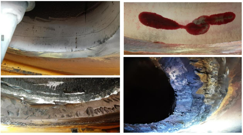
Close-up view of the cracks discovered in the straddle carrier’s steering pin connection
To achieve this, a detailed finite element analysis (FEA) model of the straddle carrier was developed, with particular emphasis on accurately representing the steering pin connection geometry, material properties, and boundary conditions. This high-fidelity model enabled precise simulation of the stress state and fatigue damage accumulation in the critical region.
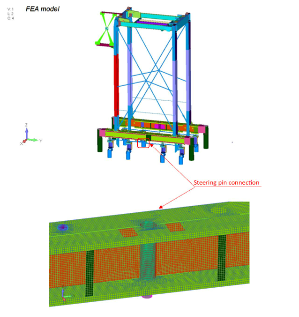
FEA model of the straddle carrier, highlighting the steering pin connection (red arrow) and the detailed meshing in the critical region.
The SDC Verifier Solution
SDC Verifier, a powerful finite element analysis software, was employed to conduct two distinct simulations:
1. Original Design Analysis: The initial simulation aimed to replicate the observed cracking behavior by analyzing the stress distribution and fatigue life of the original steering pin design under typical operational loads.
The varying thicknesses of the steering pin connection, as shown in the thickness plot, added another layer of complexity to the FEA modeling process.
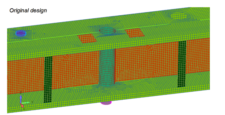
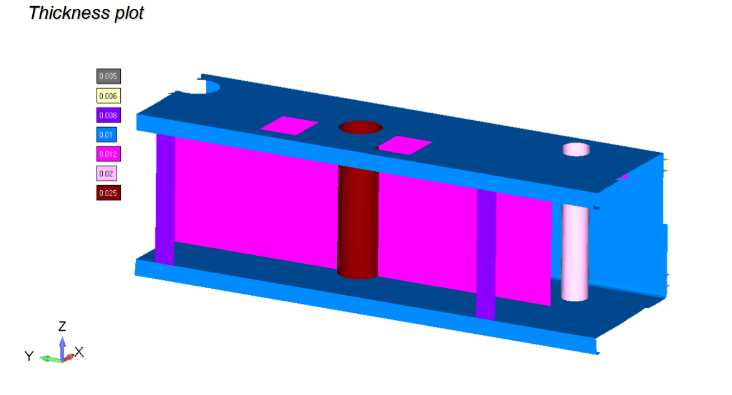
Image1. FEA model of the original steering pin connection, illustrating the mesh and boundary conditions used in the analysis.
Image 2. Thickness plot of the steering pin connection, showcasing the varying thicknesses of different components.
2. Reinforced Design Analysis: The second simulation evaluated the effectiveness of the proposed reinforced design, which involved increasing the plate thicknesses in critical areas of the steering pin connection, in mitigating stress concentrations and improving fatigue performance.
SDC Verifier’s capabilities allowed for precise modeling of the steering pin connection, including the varying thicknesses as shown in the thickness plot.
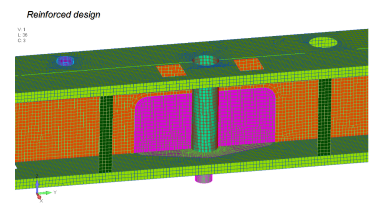
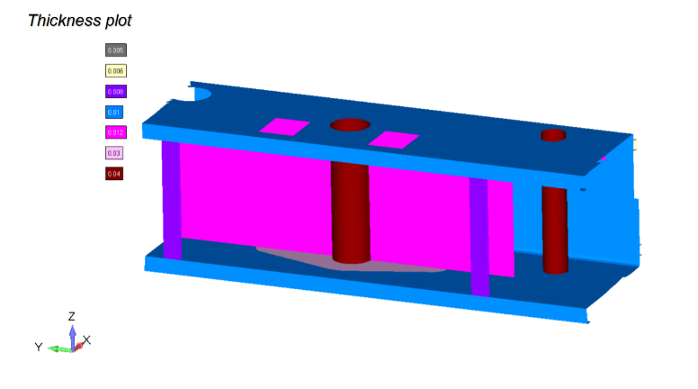
Image 1. FEA model of the reinforced steering pin connection, showing the increased plate thicknesses (highlighted in purple) aimed at reducing stress concentrations.
Image 2. Thickness plot of the steering pin connection, showcasing the varying thicknesses of different components.
SDC Verifier’s capabilities extend beyond stress analysis. The software facilitated comprehensive assessment by performing both static stress checks and fatigue summation checks in accordance with the stringent requirements of the EN13001 standard, ensuring the structural integrity of the component.
Results and Discussion
The FEA results provided valuable insights into the structural behavior of both the original and reinforced steering pin designs.
-
Original Design: The analysis of the original design revealed stress concentrations in the vicinity of the observed cracks, corroborating the real-world failure. Fatigue life predictions indicated a high likelihood of crack initiation and propagation under cyclic loading, with a maximum fatigue utilization factor (UF) exceeding 1. This further validated the accuracy of the simulation and highlighted the need for design improvement.
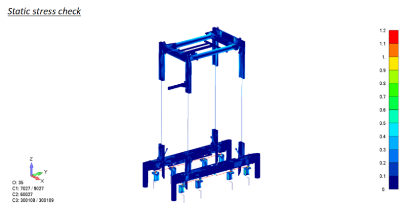
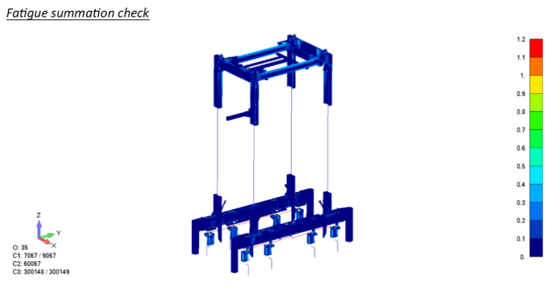
Image 1. Static stress check results for the straddle carrier’s general structure, showing the distribution of stress under operational loads. (e.g., blue indicating low stress, red indicating high stress)
Image 2. Fatigue summation check results for the straddle carrier’s general structure, illustrating the accumulated fatigue damage.
-
Reinforced Design: The reinforced design, with increased plate thicknesses in critical areas, exhibited a marked reduction in peak stresses, effectively mitigating the stress concentrations observed in the original design. The fatigue analysis demonstrated a significant improvement in fatigue life, with the maximum UF now well below 1, indicating that the design is safe against fatigue failure. This translates to a substantial extension of the component’s service life.
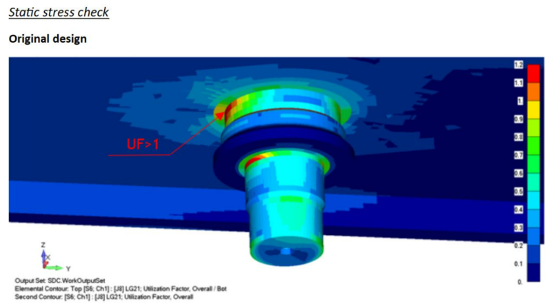
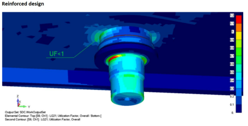
Image 1. Static stress check results for the original steering pin design, showing areas of high stress concentration (UF > 1).
Image 2. Static stress check results for the reinforced steering pin design, demonstrating a reduction in stress levels (UF < 1).
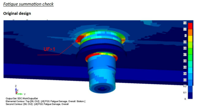
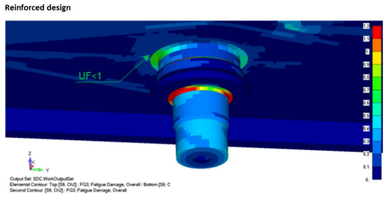
Image 1. Fatigue summation check results for the original steering pin design, highlighting areas with high fatigue damage (UF > 1)
Image 2. Fatigue summation check results for the reinforced steering pin design, showing a significant reduction in fatigue damage (UF < 1).
The results unequivocally demonstrate the efficacy of the reinforced design in addressing the cracking issue and enhancing the structural integrity of the steering pin. The reduction in stress levels and improved fatigue performance, evidenced by the quantitative UF values, directly contribute to a longer, safer operational lifespan for the component.
Conclusion
The FEA analysis successfully replicated the real-world cracking behavior observed in the original steering pin design, underscoring the accuracy and predictive capabilities of the simulation. The correlation between the high fatigue damage predicted by the analysis and the actual cracks serves as a testament to the effectiveness of the FEA methodology.
The reinforced design, validated through FEA, effectively addressed the cracking problem by significantly reducing stress concentrations and fatigue damage. The resulting stress levels and fatigue life now fall comfortably within acceptable limits, ensuring the structural integrity of the component.
The successful implementation of the reinforced design not only mitigates the immediate safety risk but also extends the operational lifespan of the steering pin, providing a substantial return on investment for the client. Moreover, the improved safety margins instill confidence in the reliability and longevity of the straddle carrier, contributing to a safer and more efficient operation.


