API RP 2A-WSD (21st, 2007)
API RP 2A-WSD (21st, 2007) edition - recommended practice for planning, designing and constructing fixed offshore platforms released December 2000 (Errata and supplement 3, October 2007).
The standard supports calculations for circular tubes only.
To add the standard execute from the ribbon:
![]()
Press  to Set Standard Custom Settings
Safety Factors are set to Standard default values. It is not necessary to change them.
According to the calculation procedure, Beam Length for Y and Z direction is required. Data from Beam Member Finder is used automatically.
If beam members are not recognized press  .
.
Formulas (3.3.1-5) and (3.3.1-6) should be applied to cylindrical piles. By default, the calculations are skipped and a user should define when a member is treated as a pile.
![]()
Standard uses material data (Yield/Tensile) in calculations. Wizard checks if the values are defined for all materials.
It is possible to use API 2A RP (21st, 2007) in combination with AISC ASD 89 Members (9th, 1989) standard.
Set option Use AISC 89 for non-tubular shapes checked to use the standard for non-tubular elements.
Press  to define settings.
Note: If the AISC 89 is included - 3 standards will be created:
- API RP 2A-WSD - circular tubes are calculated according to API WSD;
- AISC ASD 89 - all supported shapes are calculated according to AISC ASD 89;
- AISC and API - combined standard where results for circular tubes are taken from API RP 2A-WSD and results for other supported shapes - according to AISC 89.
The value 12345678 is used when the calculations cannot be performed due to geometrical limitations or calculations are out of scope.
Joint Check
Joint Check is a part of theAPI RP 2A-WSD standard but is available for Custom Standard. To create a new Joint Check execute from the checks context menu of a respective standard.
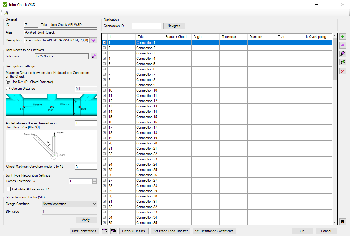
Press  to automatically highlight single Connection selected in the table.
Recognition Settings are described in Common Options chapter.
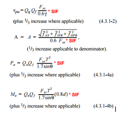
Stress Increase Factor (SIF) - resistance increase factor according to selected Design Condition:
- Normal Operation - SIF = 1;
- Survival - SIF = 1.3333;
- Accidental - SIF = 1.6667;
- Custom - set custom value;
In formulas it is implemented as following:
Set and press to display connection in the table.
Joint check is based on connections. Each connection is a set of elements near joint node (see Joints Finder). Connections consists of Chord and braces. Brace contains only 1 element with ID defined in brackets (#). Connection can contain braces from the both sides of the chord. Information is displayed in second brackets: U- upper braces; L- lower braces;
Press  to find all connections of the model. Window with connections that are recommended to be checked manually will be displayed:
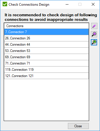
Connection has to be checked when:
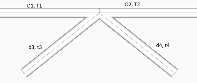
- D1 = D2 = d3 = d4, T1 = T2 = t3 = t4
- D1 = D2 = d4, T1 = T2 = t4, d3 > D1
- D1 = D2 = d3 = d4, T1 = T2 = t4, t3 > T1 according to the following image
 - Add new connection manually:
 - edit selected connection;
 - preview highlight selected connection;
 - preview only selected connection;
 - remove selected connection;
 - plot all connections values in colors + Labels with IDs;
 - show information about all connections;
 - hide information of all connections.
![]() - clear all calculations for loads;
- clear all calculations for loads;
Edit Connection
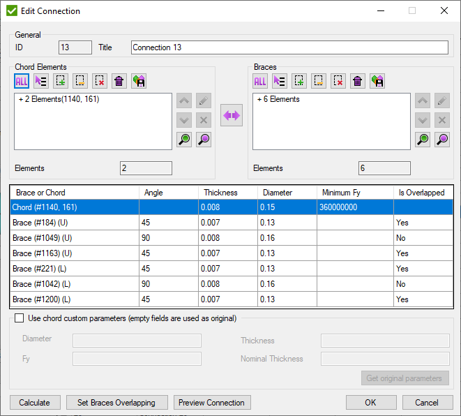
Pick Chord elements and braces (each brace consist of 1 element) and press to preview connection properties.
 - swap chord and brace selections
Press to highlight connection on the model.
- open window to set the overlapping brace. Is enabled only if one brace overlaps another one in connection:
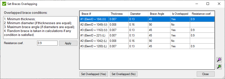
Resistance Coef. - AISC resistance factor for the weld (Φsh).
- set to the selected braces if they are overlapped.
 - set resistance
coefficient for overlapped braces:
- set resistance
coefficient for overlapped braces:
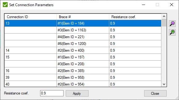
All overlapped braces are displayed in the list with the related connection ID.
Fill Resistance coef. and press to set the coefficient to all selected braces.
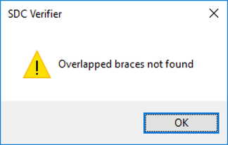
If no overlapped braces are found, a message will be displayed:
![]() - display a window to set Load transfer (section 4.3.2 in standard) for braces of connections which contain:
- display a window to set Load transfer (section 4.3.2 in standard) for braces of connections which contain:
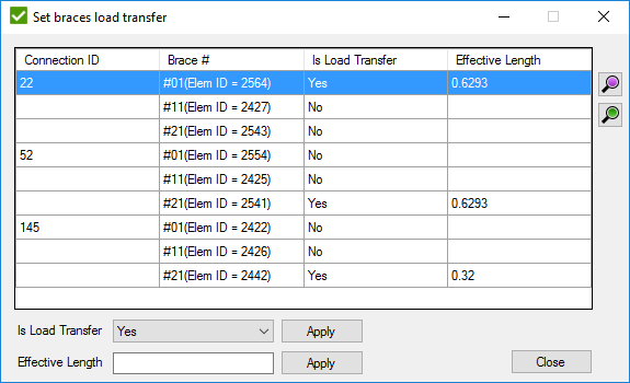
If load transfer is set to "No", formulas 4.3.2-1,2 will not be applied to the calculations, even if they match the conditions.
It is possible to change the Effective Length manually. Set value to Effective Length field and press button to set value to the selected braces.
According to standard, joint types are defined by the following rules:
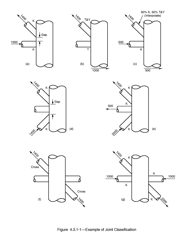
Joint type is based on type of loading. By checking if forces of connection are balanced joint types are classified on K, TY and X (Cross).
K - tension and compression loads are balanced.
TY - tension or compression load goes as a shear force in a chord.
X (Cross) - Connection has to contain braces from the both sides to check on a cross joint. If balanced forces of all braces on one side and balanced forces of all braces of other side are equal then all braces are classified as X (Cross).
Interpolation - the order of joint type recognition is following: K -> X (Cross) -> TY. Each brace can have all 3 types of the joint type taken as a percentage of the axial load of a brace to a summation of all braces loads.
Note: If brace has 0 force joint type for such brace is set to TY.