Views
Views - a set of options that defines how plots are displayed.
Execute from the ribbon:
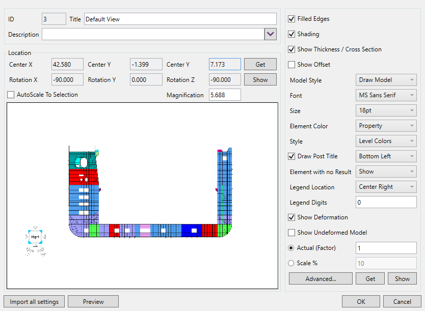
Location - a center, rotation angles, and magnification information. To get the center, rotation angles and magnification of the active view from the model use the button (the model position will be displayed on the form).
AutoScale To Selection option allows using one view for different Model parts. The view is rotated and then it is scaled to the plot selection. Press to set and preview current location in the model.
Settings - a set of base view settings for font and model overview. Use to import settings from the current view in the model. Press to set and preview the current settings in the model.
Press to import the location and the settings from active view in the model;
Press to display location and settings;
Main options
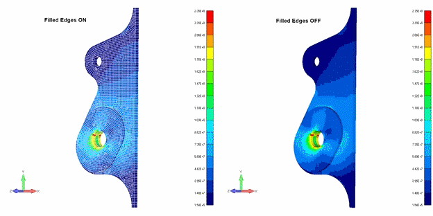
Filled Edges - the element boundaries are drawn.
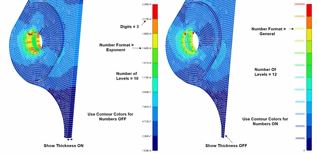
Show Thickness / Cross Section - displays the plane elements with thickness and the line elements with shape.
Legend Digits - how many digits after the dot have to be used in the exponent number format (e.g. 2.536E+6, Digits = 3)
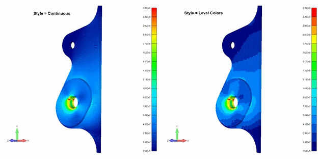
Style - continuous use of a smooth gradient and level colors don't use the gradient.
Legend Location - selects the position of the legend in the plot (bottom, right, etc.)
Advanced Options
Advanced options - background, fem load vectors, legend colors and levels:
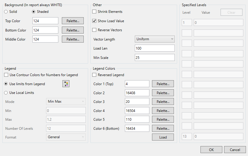
Background can be Solid (one color) and Shaded (gradient)
Note: When generating a report the background settings are ignored and white color is used;
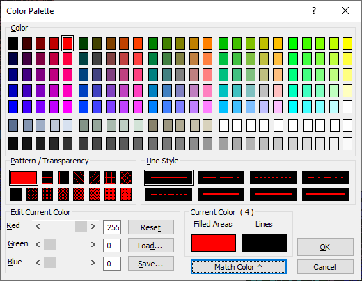
 - pick a color:
Legend
It is possible to set the custom settings of the legend for better results overview.
Use limits from Legend Settings - use settings from project Legend Settings.
Note: Project legend settings contain the settings for different categories. There is no need to create different views for the displacement or stress plots, for example, but set the respective settings.
 - opens the window to change the project legend settings;
Use Contour Colors for Numbers for Legend - Use Contour Colors for Numbers for Legend
Use Local Limits - set a static legend for all the plots with a current view;
Mode - select the legend values displaying type:
- Automatic - use the minimum and maximum values of the plot for the legend;
- Max-Min - set the custom minimum and maximum values of the legend;
- User Defined - set the custom values for each level of the legend;
- Max threshold - display the maximum threshold instead of the maximum value in the legend;
- Min/Max threshold - display the minimum and maximum threshold instead of the values in the legend;
- Min threshold - display the minimum threshold instead of the values in the legend;
- Visible Min/Max - use the minimum and maximum values of only visible part of the model the plot for the legend (e.g. material or property visibility is turned off);
Number of Levels - how the colors are used for the plot.
Format - the legend numbers can be in the exponent (e.g. 2.42E+6) and the general (e.g. 242000000) formats.
Legend Colors
Define custom colors of the legend.
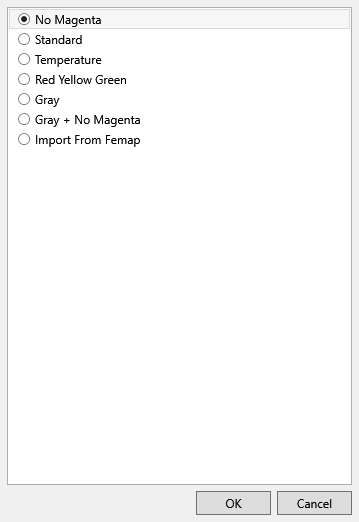
Reversed Legend - change the order of the colors of the legend and vice versa.
Press button to select the legend color scheme from the predefined list.
Other
Shrink Elements - reduces the size of the elements;
Reverse vectors - display load vector to the node when the option is checked (from the node when unchecked);
Vector length - uniform or scale by magnitude, which scales vector length based upon the magnitude;
Load Len - constant length of the load vector;
Minimum scale - all load vectors which would fall below the minimum value are scaled to the minimum. This will prevent a visual loss of small loads in a large model.
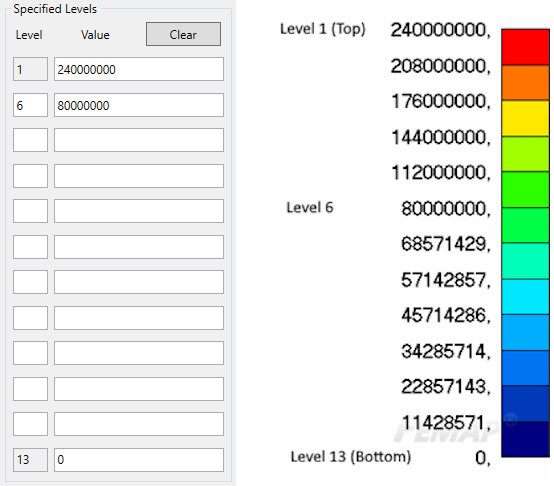
Specified Levels
It is possible to set the custom values for each level if the local limits mode in the Legend is set to the User Defined.
Note: Level 1 corresponds to the highest legend value (top level). It is possible to set the values only for necessary levels. The values for other levels will be calculated using the first and the last level.
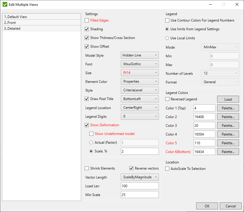
Multiple View Editing
It is possible to edit parameters for selected views at once. If option is different for the selected views it is displayed with red color.
Execute from the tree: