F.E.M. 1.001 (3rd, 1998)
F.E.M. 1.001 (3rd, 1998) performs the static stress check and fatigue check for the steel structures of crane and crane equipment. Fatigue calculations are performed according to the Allowable Stress Design method (ASD).
To add F.E.M. 1.001 standard execute from the ribbon:
Press  to Set Standard Custom Settings
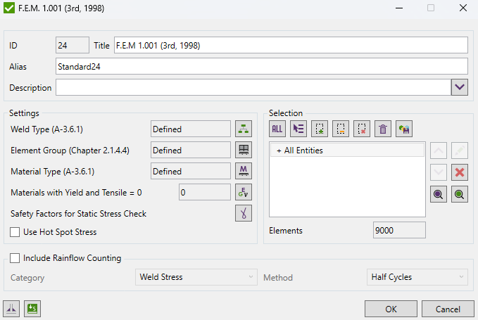
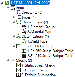
To perform the fatigue check three classifications should be defined: Weld Type, Element Group and Material Type.
Weld Type - also called Notch Case, determines which elements belong to what weld type (K0-K4 - joints affected by welding, W0-W2 - elements and joints, not affected by welding). Weld Type depends on the shape, structural design, whole pattern or type and quality of the welds.
Element Group - depends on the Load Spectrum and Class of Utilization (number of cycles). Can be set from E1 to E8.
Load Spectrum:
The load spectrum characterizes the magnitude of the load acting on the component during its total duration of use.
| Load Spectrum | Remarks | ||
|---|---|---|---|
| P0 | Very light | P=0 | Crane by exception loaded with the working load, and as a rule, with very light loads |
| P1 | Light | P=1/3 | Crane sometimes loaded with the working load, and as a rule with loads of about 1/3 of the working load |
| P2 | Moderate | P=2/3 | Crane repeatedly loaded with the working load, and as a rule with loads between 1/3 and 2/3 of the working load |
| P3 | Heavy | P=1 | Crane frequently loaded with the working load |
Class of utilization (number of cycles):
| Symbol | Total duration of use number n of stress cycles) | ||||
|---|---|---|---|---|---|
| B0 | n | ≤ | 16 000 | ||
| B1 | 16 000 | < | n | ≤ | 32 000 |
| B2 | 32 000 | < | n | ≤ | 63 000 |
| B3 | 63 000 | < | n | ≤ | 125 000 |
| B4 | 125 000 | < | n | ≤ | 250 000 |
| B5 | 250 000 | < | n | ≤ | 500 000 |
| B6 | 500 000 | < | n | ≤ | 1 000 000 |
| B7 | 1 000 000 | < | n | ≤ | 2 000 000 |
| B8 | 2 000 000 | < | n | ≤ | 4 000 000 |
| B9 | 4 000 000 | < | n | ≤ | 8 000 000 |
| B10 | 8 000 000 | < | n |
Element Group (Table T.2.1.4.4):
| Stress Spectrum class | Class of utilization | ||||||||||
|---|---|---|---|---|---|---|---|---|---|---|---|
| B0 | B1 | B2 | B3 | B4 | B5 | B6 | B7 | B8 | B9 | B10 | |
| P1 | E1 | E1 | E1 | E1 | E2 | E3 | E4 | E5 | E6 | E7 | E8 |
| P2 | E1 | E1 | E1 | E2 | E3 | E4 | E5 | E6 | E7 | E8 | E8 |
| P3 | E1 | E1 | E2 | E3 | E4 | E5 | E6 | E7 | E8 | E8 | E8 |
| P4 | E1 | E2 | E3 | E4 | E5 | E6 | E7 | E8 | E8 | E8 | E8 |
Material Type - define which steel is used St37 or St52.
Standard uses material data (Yield/Tensile) in calculations. Wizard checks if the values are defined for all materials.
By default, the full model is set for the selection, but it is possible edit the selection.
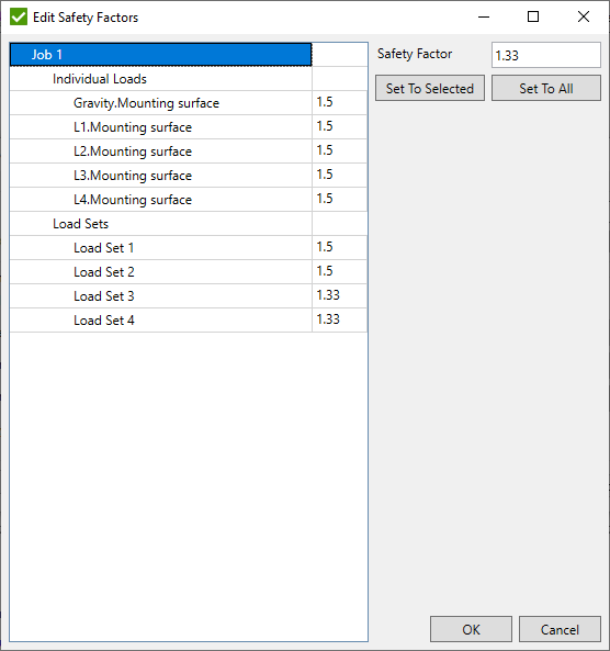
Press  to define safety factors for static stress check for individual loads and loads sets should be defined:
Use Hot Spot Stress - use Hot Spot Stress results for locations defined in Weld Finder Tool or Weld Stress results in the fatigue checks.
The fatigue calculations (2..Fatigue) are performed on Load Group only, stress range from load group is required. Check "3..Fatigue Summation" performs additional calculations and sum damage from different load groups based on stress history defined in Fatigue Group.
Include Rainflow Counting - include rainflow fatigue summation check with defined result category and method from which Rainflow Counting data will be used.
Note: category options for fatigue are Weld Stress or Hot Spot Stress.
Note: this option is available only for Enterprise licensing.
Static Check
The allowable stress is limited <0.7.For steels with high elastic limit allowable stress is corrected with formula in chapter 3.2.1.1
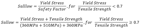
For the shear direction the allowable stress is divided on √3
Fatigue Check
The Kappa factor is the ratio between minimum and maximum stresses

For K-factor [-1;0]:
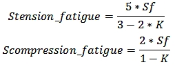
For K-factor (0;1]:
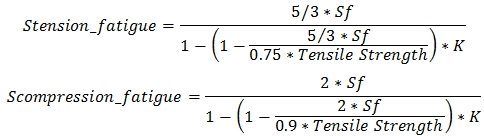
Where Sf – the allowable stress fatigue when K=-1. The Stress fatigue can be set by the exact value or by setting the crane group and the weld type
Coefficient = 1 – for the normal and equivalent stresses.
Coefficient = – for the shear stress with the weld classification K0-K4.
Coefficient = – for the shear stress the with weld classification W0-W2.
Utilization factor fatigue (is calculated for the directions X, Y, Z, XY, YZ and ZX):
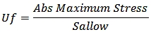
Combined utilization factor fatigue is calculated using the following formula (the sign of Ufx, Ufy and Ufz are taken into the account) :

Maximum Utilization factor fatigue:
