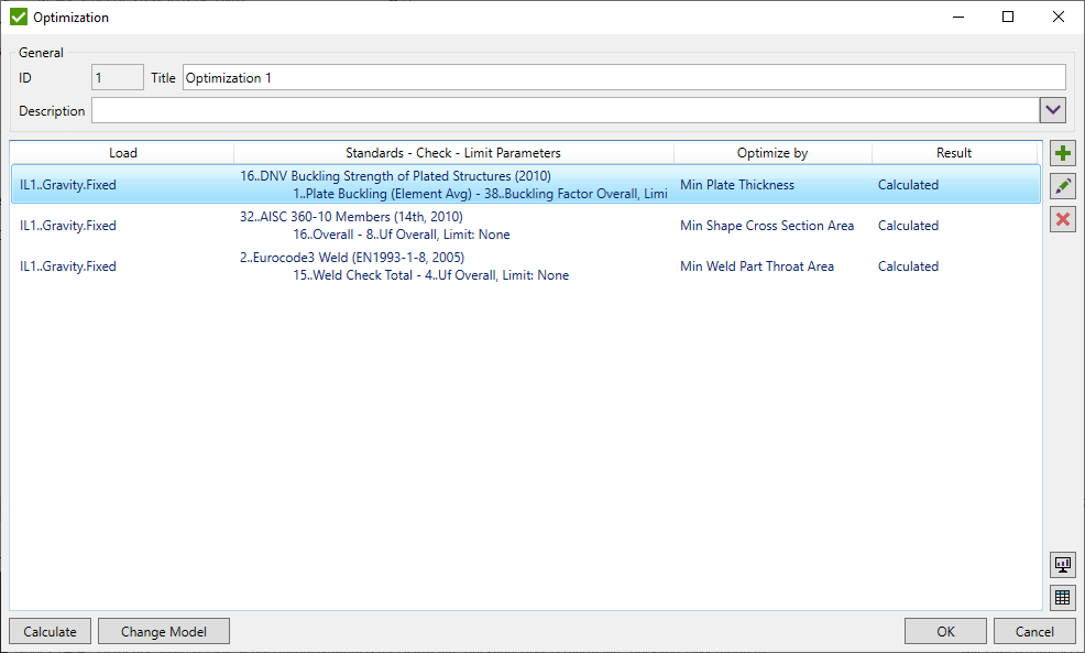
Optimization Tool
Optimization Tool allows to take the best design decision for the structure by calculating different combinations of design input.
To add new Optimization Tool execute from the ribbon.
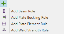 -
add Optimization Rule by type;
-
add Optimization Rule by type;
 - edit selected Optimization Rule.
The results of selected rule will be cleared;
- edit selected Optimization Rule.
The results of selected rule will be cleared;
 - remove selected Optimization Rule.
Press to perform calculations. After calculations are performed and optimal result is calculated it is possible to Change Model to apply optimal settings of the selected rule to the model. Depending on the type of the rule the following changes can be applied:
- Beam Rule - new beam properties with optimal shapes and/or materials with optimal yield stress / young modulus will be created;
- Plate Buckling / Plate Element Rules - new plate/shell properties with optimal plate thickness and/or materials with optimal yield stress / young modulus will be created;
- Weld Strength Rule - optimal weld part settings will be applied in Weld Finder Tool.
Press  to plot the optimal result of selected rule on the model.
Results will be shown only for the part of the model to be optimized;
to plot the optimal result of selected rule on the model.
Results will be shown only for the part of the model to be optimized;
It is possible to preview optimal or all results of selected rule in the table:
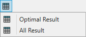
Optimal Result
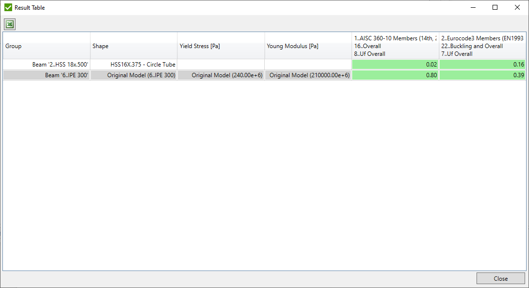
Show the best matching result on selected parameters for all grouped variables. Example of the table calculated for Beam Rule:
All Results
Show all results over all created optimization variables. Example of the table calculated for Beam Rule:
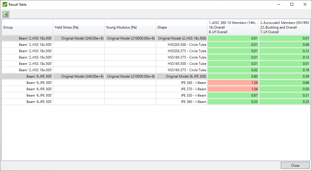
Note: Original model values are displayed in round brackets if all elements in selection have the same value (e.g. Yield Stress). Count of different values will be displayed otherwise.
Optimization Rule
Optimization Rule consists of a set of conditions that represent the part of the model, the type of optimization and the referring parameters (usually utilization factors) of design standards to be optimized.
The following types of the rules can be created:
- Beam Rule - beam/bar element cross section, yield stress and young modulus can be optimized;
- Plate Element Rule - plate/shell element thickness, yield stress and young modulus can be optimized;
- Plate Buckling Rule - plate buckling plate thickness, yield stress and young modulus can be optimized;
- Weld Strength Rule - weld type and dimensions (leg sizes, throat thickness etc.) can be optimized.
Only one rule of each type can be created within one optimization tool. Plate element and Plate buckling rules cannot be created within one optimization tool.
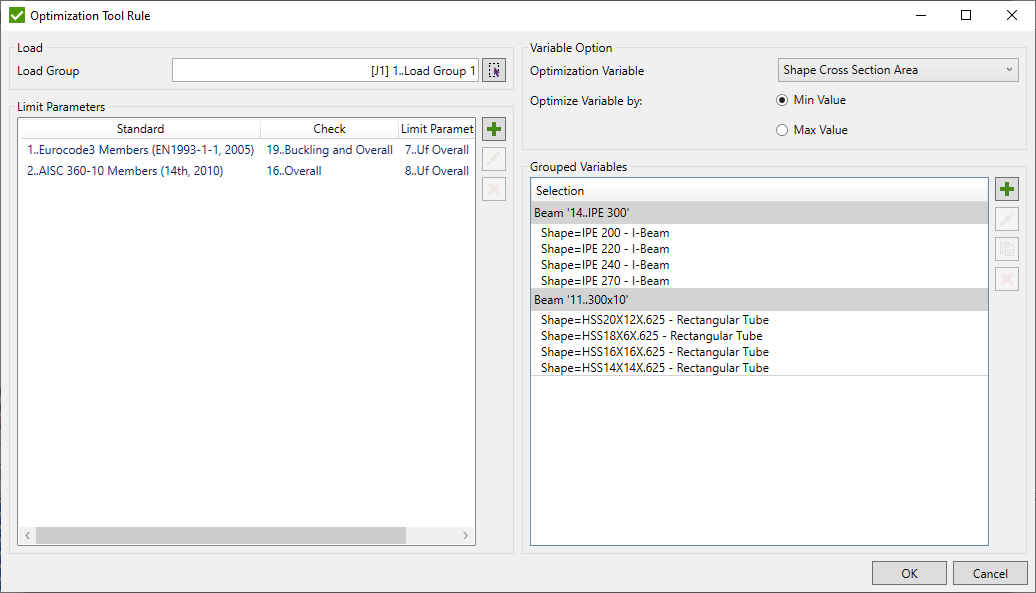
Select Load using Load Selector for calculating the selected standards.
Parameters from the design standards can be defined using Limit Parameters.
Grouped Variables - define variables for optimization parameters that depend on the type of the rule;
Variable Option - select the type of the variable to be optimized that depend on the type of the rule;
Limit Parameters
Select parameters to optimize from the respective design standards. It is possible to add several parameters to get the most applicable results according to different design standards.

 - select parameter to be optimized from
the existing standard;
- select parameter to be optimized from
the existing standard;
- change selected parameter;
- remove selected parameters;
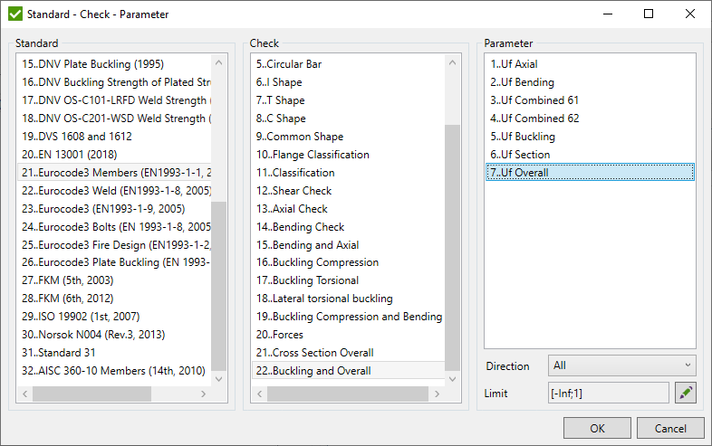
Select Standard, Check, choose Parameter and Direction ('All' direction is displayed if check is not calculated over directions) to be optimized.
Note: Only checks that fit the type of the rule (beam, plate buckling etc.) will be displayed in the list.
Note: If the parameter had already been added it will not be shown in the list when adding another parameters.
Define Limit using Limits Control. Limits are used to filter results and find the best matching optimal result. A result that passes the limits and matches the variable type (e.g. Min Cross Section Area) will be chosen as an optimal result.
Beam Rule
Beam Rule is used to optimize beam/bar element cross section, yield stress and/or young modulus. It is typically used for beam buckling standards. Common options are described in Optimization Rule
Following variables in formulas of the standards will be replaced with the values defined in optimization during the calculations: Yield, Young and also all variables related to shape dimensions and properties (e.g. Area, Iyy, H, T etc.). Variables are described here.
Variable Option
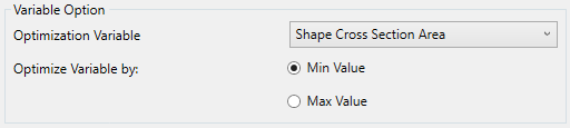
Optimization Variable - select the type of the variable to be optimized (Shape Cross Section Area, Young Modulus, Yield Stress);
Optimize Variable by - find an optimal result based the on min/max value of the variable type. For example to optimize the structure according to the lowest weight - select Min Value of Shape Cross Section Area.
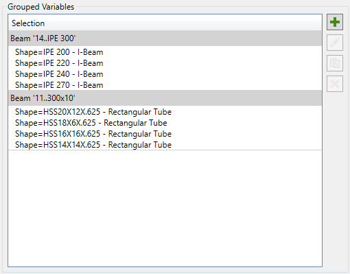
Grouped Variables
Define variables for the parts of the model to be optimized that will replace the original model settings (shape, yield stress or young modulus) in calculations. Each created variable is a separate result of the tool.
- remove selected variables;
 - copy existing variable:
Define Selections using Selection List Control. Copy settings of selected variables and apply to the new selections.
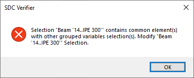
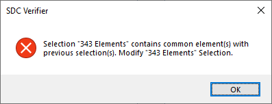
Note: If common elements exist in selections of different variables, an error message will be shown:
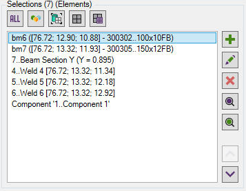
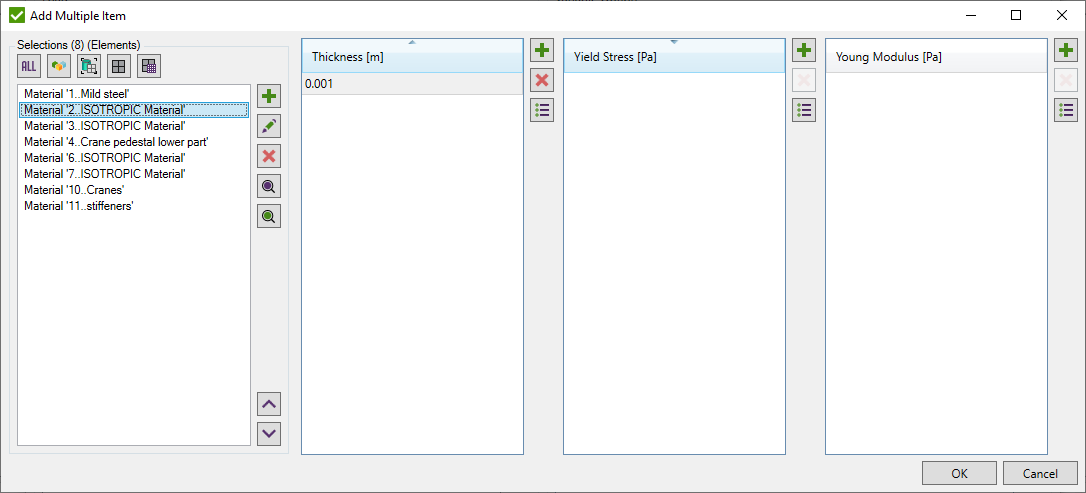
- create multiple variables:

Define Selections using Selection List Control. Each selection represents part of the model to be optimized.
Note: If common elements exist in selections of different variables, an error message will be shown:
Shape - add a list of shapes that will be replaced for selected selections from the Shape Library. It is possible to use a different type of shape than in the existing model;
Orientation - Select Left, Right, Up, Down or Original (the same orientation as current cross section in the model) cross section orientation that is applied for all selected shapes from the library. For example H cross section can be used as I with modified orientation.
Orientation is not applied if Nastran shapes are selected from the library as Y axis is always 'Up' for such shapes.
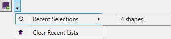
Recent Shapes that were used withing the project is displayed in the recent menu:
Yield Stress - create a list of variables that will replace Yield Stress of the material in all defined selections;
Young Modulus - create a list of variables that will replace Young Modulus of the material in all defined selections;
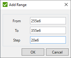
 - Add range of Yield Stress/Young Modulus values:
Note: Optimization result will be calculated for all combinations of Selection + Shape + Yield Stress + Young Modulus.
Edit Grouped Variable
- edit selected variable;
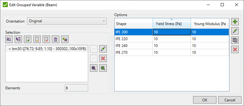
Selection - change selection using Selector Control.
All variables defined for current selection are shown in the list.
- add a single variable to the list;
- edit selected variable;
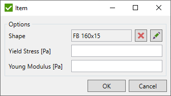
It is possible to select a single Shape from the library, set Yield Stress or Young Modulus.
 - copy selected variables;
- remove selected variables;
Plate Buckling Rule
Plate Buckling Rule is used to optimize plate thickness, yield stress and/or young modulus of buckling plates recognized by Panel Finder Tool. It is typically used for plate buckling standards. Common options are described in Optimization Rule
Following variables in formulas of the standards will be replaced with the values defined in optimization during the calculations: Plate.Thickness, Plate.ThicknessRatio, Yield, Young. Plate stresses will be automatically recalculated if Plate.ThicknessRatio is used in formulas. Variables are described here.
Variable Option
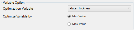
Optimization Variable - select the type of the variable to be optimized (Plate Thickness, Young Modulus, Yield Stress);
Optimize Variable by - find an optimal result based the on min/max value of the variable type. For example to optimize the structure according to the lowest weight - select Min Value of Plate Thickness.
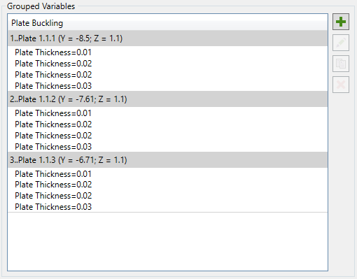
Grouped Variables
Define variables for the buckling plates to be optimized that will replace the original model settings (plate thickness, yield stress or young modulus) in calculations. Each created variable is a separate result of the tool.
- remove selected variables;
- copy existing variable:
Select plates from the list of grouped plates by sections and panels. Copy settings of selected variables and apply to the new selections.
Note: Selected plates will not be displayed in the list of available next time the window is opened.
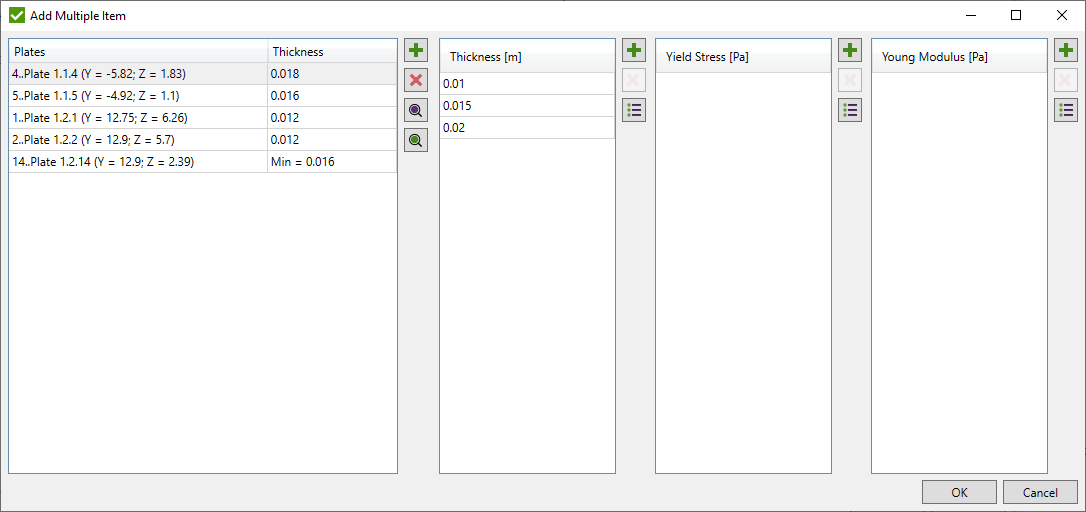
- create multiple variables:
 - select buckling plates from
Panel Finder Tool to be optimized by the following rules:
- select buckling plates from
Panel Finder Tool to be optimized by the following rules:
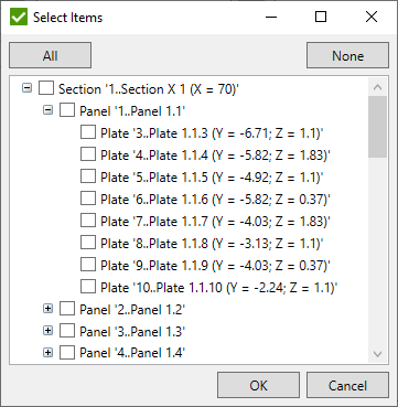
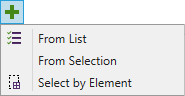
- From List - select plates from the list of grouped plates by sections and panels:
- From Selection - select plates by picking custom selection using Selector Control;
- Select by Element - select plates by picking one element of the model.
Note: Selected plates will not be displayed in the list of available next time the window is opened.
Note: Only plates that do not exist in the list will be added.
- remove selected plates from the list;
 - highlight selected plates in the model;
 - preview only selected plates in the model;
Thickness - create a list of variables that will replace thickness of buckling plate in all defined plates;
Yield Stress - create a list of variables that will replace Yield Stress of the material in all defined plates;
Young Modulus - create a list of variables that will replace Young Modulus of the material in all defined plates;
- Add range of Thickness/Yield Stress/Young Modulus values:
Note: Optimization result will be calculated for all combinations of Plate + Thickness + Yield Stress + Young Modulus.
Edit Grouped Variable
- edit selected variable;
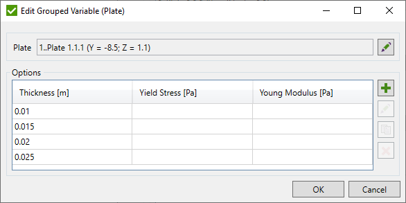
- edit selected plate;
All variables defined for current plate are shown in the list.
- add a single variable to the list;
- edit selected variable;
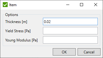
It is possible to set Thickness, Yield Stress or Young Modulus.
- copy selected variables;
- remove selected variables;
Plate Element Rule
Plate Element Rule is used to optimize plate/shell element thickness, yield stress and/or young modulus. It is typically used for fatigue standards. Common options are described in Optimization Rule
Following variables in formulas of the standards will be replaced with the values defined in optimization during the calculations: S, SMat, SWeld, SPrin, Yield, Young. Stresses will be recalculated in the formulas of the standards using the updated thickness. Variables are described here.
Variable Option
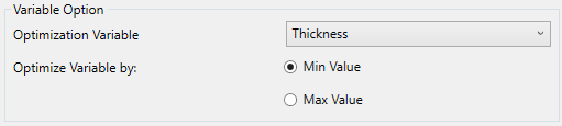
Optimization Variable - select the type of the variable to be optimized (Thickness, Young Modulus, Yield Stress);
Optimize Variable by - find an optimal result based the on min/max value of the variable type. For example to optimize the structure according to the lowest weight - select Min Value of Thickness.
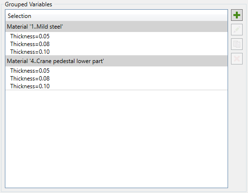
Grouped Variables
Define variables for the plate/shell elements to be optimized that will replace the original model settings (thickness, yield stress or young modulus) in calculations. Each created variable is a separate result of the tool.
- remove selected variables;
- copy existing variable:
Define Selections using Selection List Control. Copy settings of selected variables and apply to the new selections.
Note: If common elements exist in selections of different variables, an error message will be shown:
- create multiple variables:
Define Selections using Selection List Control. Each selection represents part of the model to be optimized.
Note: If common elements exist in selections of different variables, an error message will be shown:
Thickness - create a list of variables that will replace Thickness of the plate/shell elements in all defined selections;
Yield Stress - create a list of variables that will replace Yield Stress of the material in all defined selections;
Young Modulus - create a list of variables that will replace Young Modulus of the material in all defined selections;
- Add range of Thickness/Yield Stress/Young Modulus values:
Note: Optimization result will be calculated for all combinations of Selection + Thickness + Yield Stress + Young Modulus.
Edit Grouped Variable
- edit selected variable;
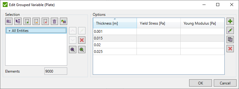
Selection - change selection using Selector Control.
All variables defined for current selection are shown in the list.
- add a single variable to the list;
- edit selected variable;
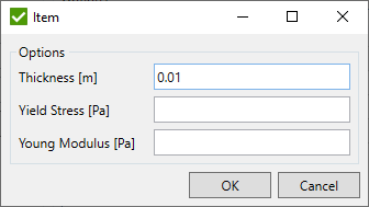
It is possible to set Thickness, Yield Stress or Young Modulus.
- copy selected variables;
- remove selected variables;
Weld Strength Rule
Weld Strength Rule is used to optimize weld parts weld type and dimensions (leg size, throat thickness etc.). It is typically used for weld strength standards. Common options are described in Optimization Rule
Following variables in formulas of the standards will be replaced with the values defined in optimization during the calculations: Weld.Type, Weld.R, Weld.S, Weld.H, Weld.Alpha, Weld.Thickness. Variables are described here.
Variable Option
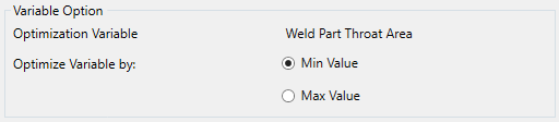
Optimization Variable - Weld Part Throat Area is used to determine the optimal result;
Optimize Variable by - find an optimal result based the on min/max value of the weld part throat. For example to optimize the weld according to the lowest material usage - select Min Value.
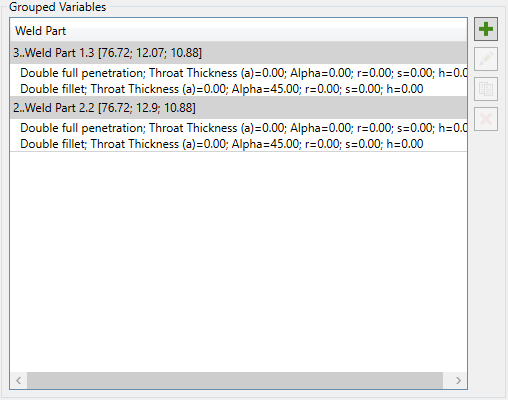
Grouped Variables
Define variables for the weld parts to be optimized that will replace the original settings in Weld Finder Tool (weld type and dimensions) in calculations. Each created variable is a separate result of the tool.
- remove selected variables;
- copy existing variable:
Select weld parts from the list of grouped weld parts by welds. Copy settings of selected variables and apply to the new selections.
Note: Selected weld parts will not be displayed in the list of available next time the window is opened.
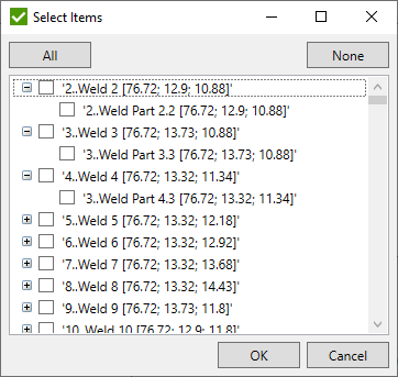
- create multiple variables:
- select weld parts from
Weld Finder Tool to be optimized by the following rules:
- From List - select weld parts from the list of grouped weld parts by welds:
- From Selection - select weld parts by picking custom selection using Selector Control;
- Select by Element - select weld parts by picking one element of the model.
Note: Selected weld parts will not be displayed in the list of available next time the window is opened.
Note: Only weld parts that do not exist in the list will be added.
Note: Only welded parts can be added to the list.
- remove selected weld parts from the list;
- highlight selected weld parts in the model;
- preview only selected weld parts in the model;
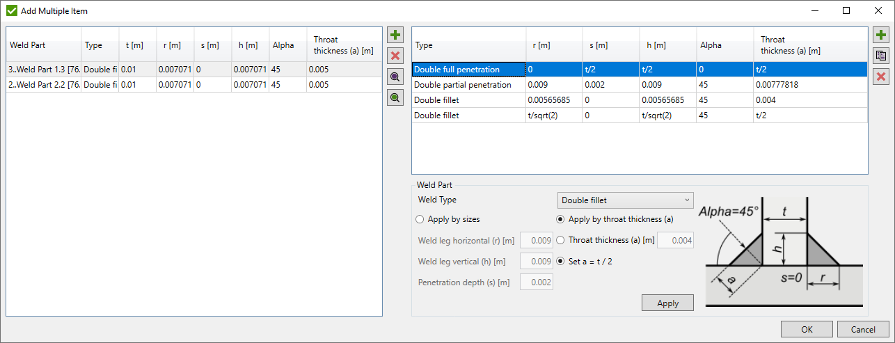
Weld Part Settings
Weld Type - weld type of the weld part to be optimized:
Double full penetration - all dimensions are calculated using weld part thickness as shown in the picture below:
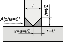
Note: Values s, h, a = t/2 will be displayed in the table because the values can be different for selected weld parts;
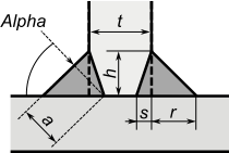
Double partial penetration - weld leg horizontal (r), weld leg vertical (h) and penetration depth (s) are input parameters. Alpha and throat thickness (a) are calculated automatically.
Double fillet - alpha is automatically set to 45°. If weld leg horizontal (r) = weld leg vertical (h) are inputs - throat thickness (a) is calculated automatically and vice versa.
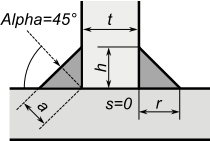
If Apply by Throat Thickness is selected, it is possible to set custom throat thickness (a) or use a half of weld part thickness (t).
Note: If Set a = t/2 option is selected, values a = t/2 and r = h = t / sqrt(2) will be displayed in the table because the values can be different for selected weld parts;
Press Apply to apply weld part settings to selected in the list.
- add new weld part settings to the list;
- copy selected weld part settings;
- remove selected weld part settings;
Note: Optimization result will be calculated for all combinations of selected weld parts and new weld part settings.
Edit Grouped Variable
- edit selected variable;
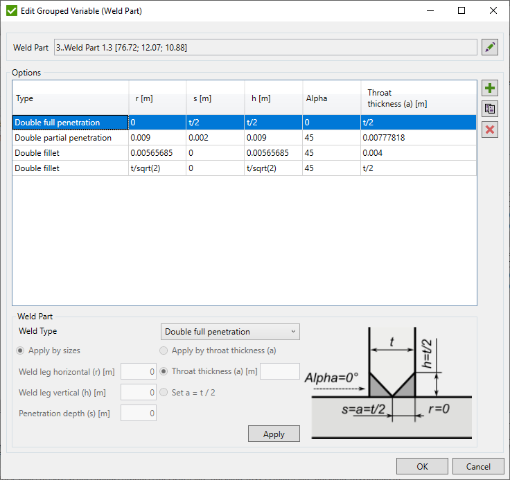
Options are described above.
- edit selected weld part;