FEM Loads
FEM Loads are the loads read from the model.
The loads with only applied force/moment on nodes can be converted to Multi Nodal Forces (it is possible to edit few loads at once).
The following types of loads can be created in SDC Verifier:
- Body Load;
- Nodal;
- Elemental;
- On Point;
- On Curve;
- On Surface;
- Wind;
- Buoyancy;
- Tank Load;
- Wave;
- Multi Nodal Force;
- Multi Selection Nodal Force.
FEM Load definitions descriptions are not loaded automatically, only by request (can have an impact on project loading performance). Press to read the description.
If FEM Loads were created/removed after the project was opened in SDC Verifier execute to synchronize.
Body Load
Execute from the tree to add body load:
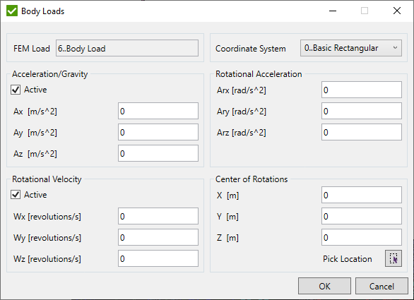
Impact every element within model and are used to simulate global movements, accelerations, or temperature changes. To assign specific load values first activate the desired body loads by checking the corresponding boxes.
- Acceleration/Gravity - used to represent gravity loads;
- Rotational Acceleration;
- Rotational Velocity - represents a rotational velocity and the associated loads that arise from centripetal acceleration;
- Center of Rotations - specifies the position of the rotation center for rotational body loads, including both rotational velocity and rotational acceleration.
 - Select Center of Rotation manually.
Nodal
Execute from the tree to add nodal load:
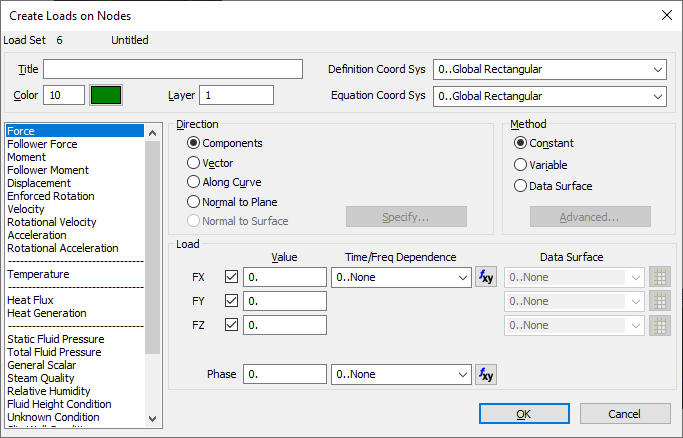
To begin, you must first decide on the type of load you intend to create. App offers thirteen (13) different nodal load types suitable for various thermal and structural analyses. These include: Force, Follower Force, Moment, Follower Moment, Displacement, Enforced Rotation, Velocity, Rotational Velocity, Acceleration, Rotational Acceleration, Temperature, Heat Flux, and Heat Generation.
Additionally, there are ten (10) other types of loads that are specific to Fluid dynamics.
Last two (2) load types are Rotor Dynamics specific, namely Unbalance Mass and Unbalance Moment.
After selecting the type of load, you can then continue to specify other necessary parameters and values for the load.
Title - enables you to provide a name for the Load Definition you are creating. If you choose not to assign a name, a default title will be generated, reflecting the type of load you have created.
Color/Palette and Layer - allow you to specify the color and layer parameters for the load you are creating.
Definition Coord Sys - becomes accessible only if you choose the Components method for specifying the direction of non-thermal load types. The components of the load are defined relative to the coordinate system you select.
Equation Coord Sys - allows you to select the coordinate system that will be used to evaluate equations for defining nodal (or elemental) loads when the Method is configured to "Variable". By default, this setting aligns with the active coordinate system in the model, rather than automatically matching the coordinate system selected in the "Definition Coord Sys".
Direction - every non-thermal type of load is considered a vector quantity, necessitating a specified direction. offers five distinct methods for setting the direction of a load: Components, Vector, Along Curve, Normal to Plane, and Normal to Surface. The Components method involves directly entering the load's components in three directions. For the other four methods—Vector, Along Curve, Normal to Plane, and Normal to Surface—you must click the "Specify..." button.
Elemental
Execute from the tree to add elemental load:
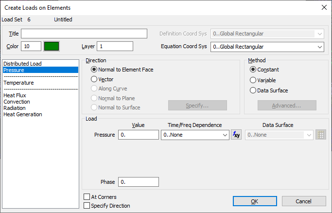
There are seven types of elemental loads: distributed loads on line elements, pressure, temperature, and four types of heat transfer loads - heat generation, heat flux, convection and radiation. The first step involves selecting the desired load type. This selection will consequently disable or conceal any controls not relevant to the type of load you're specifying. Once this is done, you can then detail the additional parameters and values associated with the load.
On Point
Execute from the tree to add on point load:

This feature allows for the application of loads directly to points, with the types of loads available being identical to those accessible through the Nodal command. All such loads are translated or expanded into nodal loads.
On Curve
Execute from the tree to add on curve load:
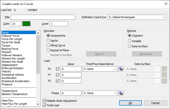
This feature enables the application of loads to curves. These loads are then transformed into nodal or elemental loads, based on the nature of the load, through translation or expansion processes.
On Surface
Execute from the tree to add on surface load:
This feature enables the application of loads to curves. These loads are then transformed into nodal or elemental loads, based on the nature of the load, through translation or expansion processes.
Wind Load
Wind Load - wind pressure (height dependent) applied to the selection. Wind can be applied to the bar, beam, plate and solid elements.
Execute from the tree to add wind:
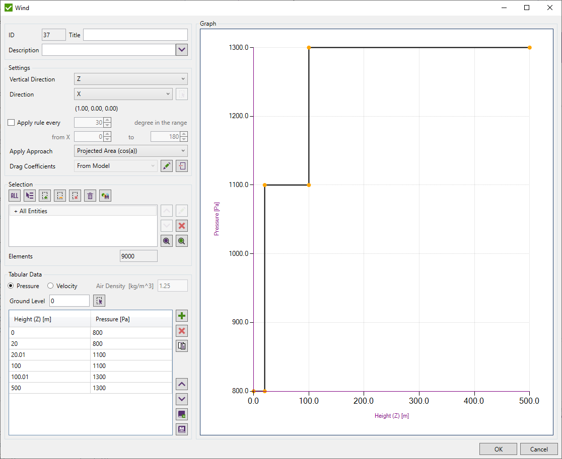
The following parameters have to be defined:
- Vertical Direction - the height uses the vertical direction to calculate pressure for the elements (in the global rectangular coordinate system);
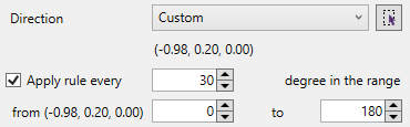
- Direction - wind direction. It is possible to select a global axis or define vector manually;
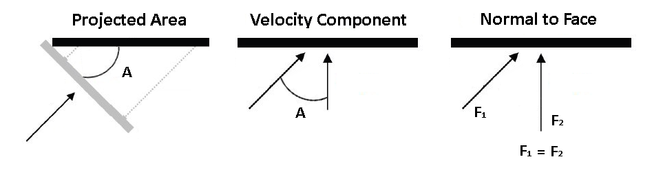
- Apply Approach - Projected Area (cos(A)), Velocity Component (cos^2(A)) or Normal to Face (cos(0));
- Drag Coefficients - use Drag Coefficients from Model or those that were used in applying of current Wind Load (Stored)
- Selection - elements to apply the wind. Selection is defined using Selector Control;
- Pressure or Velocity (including air density) - define pressure / velocity dependency from the height (user defines the direction of the vertical axis for height). Coordinates have to be in a descending order.
- Ground Level - Select the ground level for the vertical direction.
Drag Coefficients are used only for elements with cross sections. Shell and solid elements always use coefficient = 1.
 - edit Stored or Model Drag Coefficients;
 - import Drag Coefficients from other Wind load to current Wind Load;
Note: If to edit Stored Drag Coefficients - it is possible to recover them to the Model Drag Coefficients;
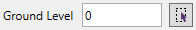
- Select Ground Level point or enter it's coordinate manually.
It is possible to apply wind in multiple direction. To do so, select Apply rule every option and set range and step of the application. It will create separate wind load for each step in the range. Directions of each wind in the range are calculated starting from the one selected in the
Press  to store pressure/velocity tabular data in the library.
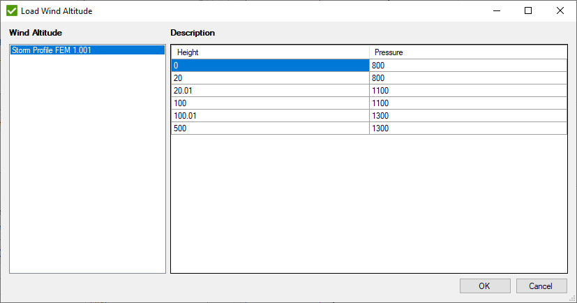
Press  to load a profile from the library:
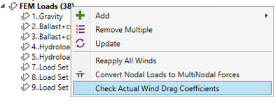
It is possible to check if all or selected Wind Load is applied with actual Drag Coefficients that are defined in the model or if all loaded elements exist in Selection of respective Wind Load.
Drag Coefficients
Drag coefficients - used to quantify the drag or resistance of an object in a fluid environment. Press to define them in Y and Z directions:
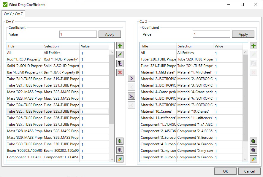
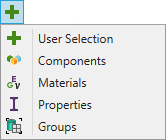
It is possible to add coefficient for a user-defined selection or based on components/materials/properties/groups selections:
 - preview only elements of the selected items;
 - highlight all elements of the selected items;
 - display a criteria plot with coefficient values of the selected items.
Wave Load
Wave Load - wave & current pressure (depth dependent) applied to the selection. Wave can be applied to the beam, bar or curved beam elements.
Execute from the tree to add wave:
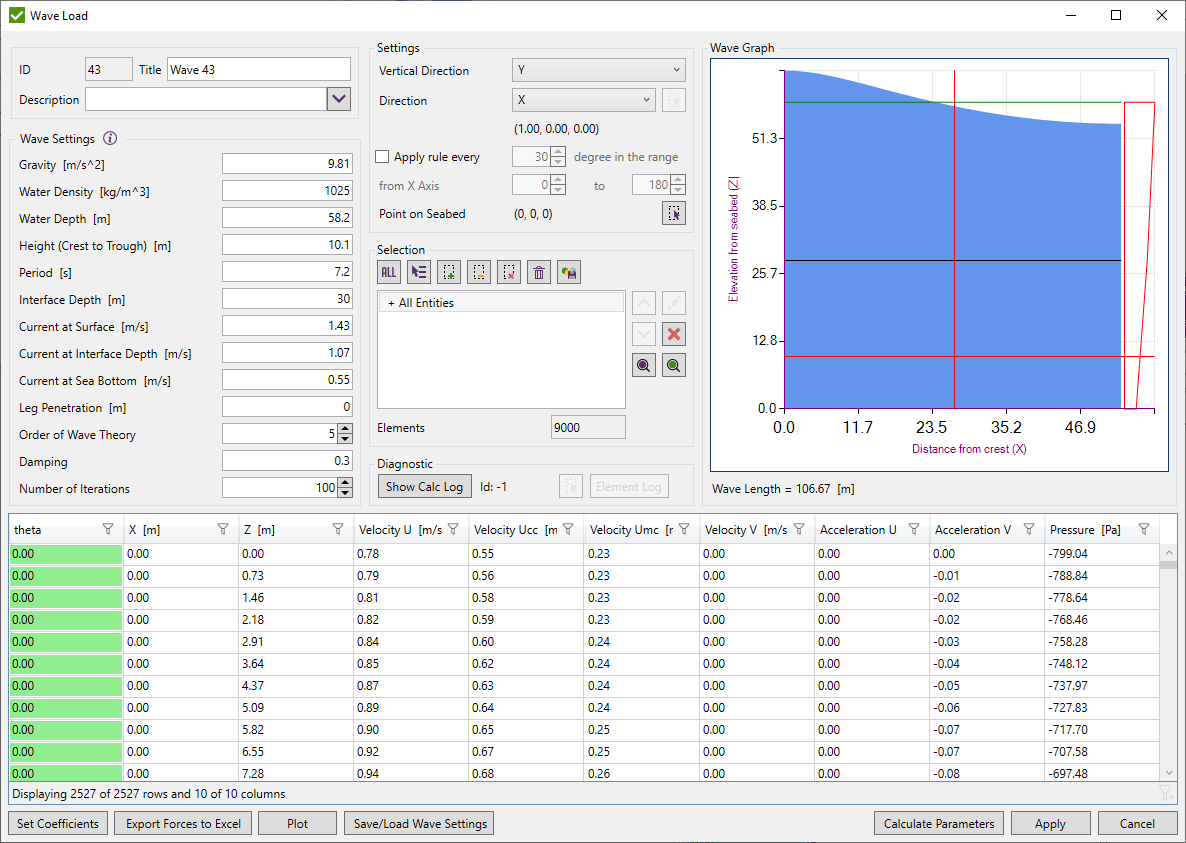
To create it the following parameters should be defined in:
- Water density;
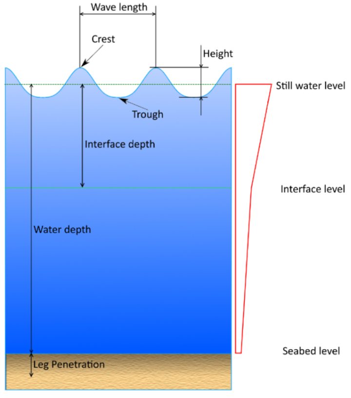
- Water depth - distance from sea bottom to still water level;
- Height (Crest to Trough) - vertical distance from Trough to Crest;
- Period - wave period (time interval between arrival of consecutive crests at a stationary point);
- Interface Depth - elevation at intermediate level in the water column used to specify the shape of the current profile;
- Current at Surface - current velocity at water surface;
- Current at Interface Depth - current velocity at Interface Depth;
- Current at Sea Bottom - current velocity at Sea Bottom;
- Leg Penetration - height of the part of the structure that is under the seabed level. Overturning moment depends on this input;
- Order of Wave Theory;
- Damping;
- Number of Iterations.
After all settings are filled in, “Calculate Parameters” button should be pressed.
Calculations are performed according to article - Chapter 36, Water waves on a bilinear shear current, Robert A. Dalrymple, p.626-641.
Result of calculations will be displayed in the grid, where:
- X - distance from crest;
- Y - distance from sea bottom (elevation);
- Velocity U - wave velocity in wave direction;
- Velocity V - wave velocity in perpendicular to wave direction;
- Acceleration U - wave acceleration in wave direction;
- Acceleration V - wave acceleration in perpendicular to wave direction;
- Pressure - water pressure.
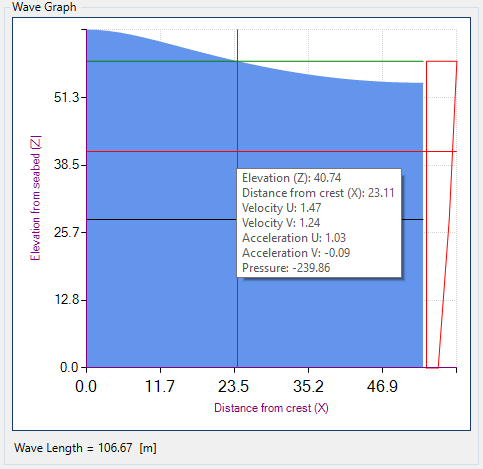
Wave Graph displays wave profile. Tooltip shows parameters of wave (velocity, acceleration etc.) at selected position.
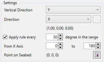
To Apply Wave Load the following parameters should be defined:
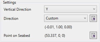
- Vertical Direction - the height uses vertical direction to calculate pressure for the elements (in the global rectangular coordinate system). Wave direction is equal to global X direction by default. If Vertical axis is equal to global X - global Y direction will be used as wave direction;
- Apply wave every step in the range - apply wave at each angle step from the original wave at the defined range. 0 degrees equals to the selected Direction. It will create separate wave load for each step in the range;
- Point on seabed - reference point on the seabed where distance from crest = 0;
- Selection - elements to apply the wave (only beam, bar or curved beam elements are used to apply the wave. Other types are skipped).
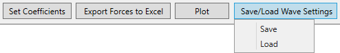
Settings can be saved/loaded from the file not to fill the values each time.
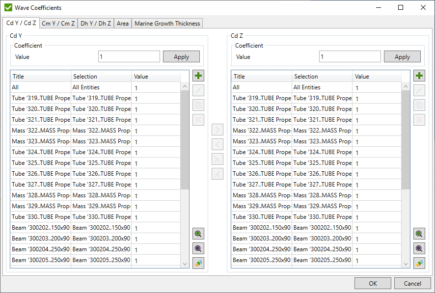
Wave Coefficients
Open Wave Drag Coefficients Form to set coefficients. All coefficients can be applied to a particular elements depending on the requirements:
- Drag coefficient - Cd Y, Cd Z;
- Inertia coefficient - Cm Y, Cm Z;
- Hydrodynamic diameter - Dh Y, Dh Z. Default value equals to the length along the shape Y and Z orientation;
- Marine growth thickness - default value = 0;
- Area - default value is calculated by the formula A = Pi * D ^ 2 / 4, where
 . It is possible to set a constant value or to take the area from the shape.
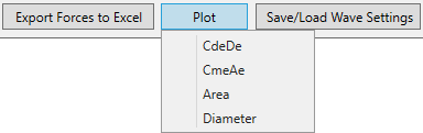
Coefficients can be plotted per elements:
Create Multiple Waves
After all the info is set up, wave forces can be applied to the structure by pressing “Apply” button. The window with all possible waves will be opened. Each row of the table represents a single wave with its parameters:
- Total Force - Summed forces of the wave in wave direction;
- Total Moment - Summed overturning moment of the wave (Leg penetration is taken into account);
- Angle - wave attack angle from the original (= 0 degrees) wave direction;
- X - distance from crest to the seabed point along the wave direction.
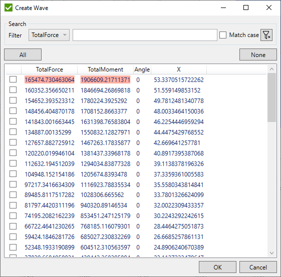
Mark selected waves and press
It is also possible to Export forces to excel to check the force before applying:
When editing a single wave, it is possible to modify all the settings and pick a custom wave direction in the settings group box:
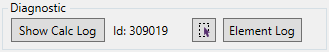
Diagnostic tool:
- Show Calc Log - display log of calculation wave parameters (calculations that occur when a Calculate button is pressed);
- Element Log - display log of how SDC Verifier apply wave load at selected element.
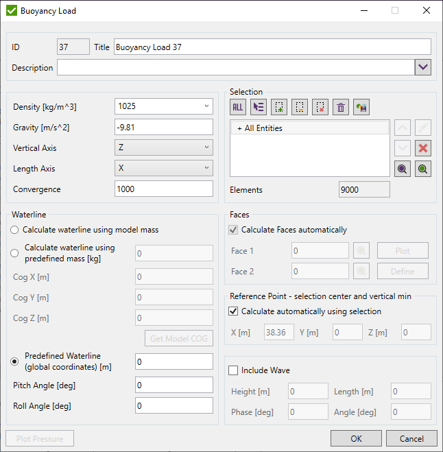
Buoyancy Load
Buoyancy Load gives a possibility to create FEM Loads with pressure acting on the plate elements and force acting on the beam elements including wave parameters.
To add Buoyancy Load select from the tree:
The applied hydrostatic pressure at the hull of a floating ship depends on the seawater density, the gravity and the height of the water. If the water line is known the pressure will be applied according to
p = ρgh
Where p is the hydrostatic pressure, ρ is the fluid density and h is the vertical distance to the waterline.
The weight distribution of a ship and the shape of the hull will determine the depth, roll, and pitch of the ship. If the waterline is unknown, then the tool will iteratively find such waterline that there will be a vertical force balance of the upward water pressure and the downward weight. It will also find the pitch and the roll with the balance of moments of the ship. With the Newton-Raphson method, the waterline will be determined with a certain amount of iterations until the balance is found within a numerical tolerance. If the balance is found then the tool has converged and the load set is created.In the Density field define the density of the water.
Gravity - gravitation (set by default -9.81 m/s^2);
Vertical Axis - waterline is defined for the vertical axis;
Length Axis - longitudinal axis of the ship.
Convergence - is accuracy for balancing when the waterline is calculated using predefined mass.
Fdiff = Pressure_Force - Predefined_Mass * Gravity;
Fdiff^2 < 100 * Convergence and Mdiff^2 < 100 * Convergence;
Waterline can be calculated using:
- Calculate waterline using model mass;
- Calculate waterline using predefined mass - the center of the gravity point should be defined;
- Predefined Waterline.
Note: If the predefined mass option is used but the mass is set to 0, then the mass of the model is used.
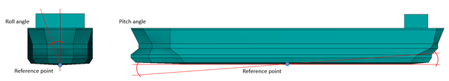
Pitch and Roll rotational angles (in degrees) around width and length axis respectively. For the predefined waterline option, it is possible to set pitch and roll manually. For other methods, they are calculated automatically.
Select the hull of a ship using Selector Control.
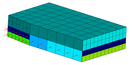
Buoyancy Load automatically recognizes element faces to apply pressure but the recognition requires perfectly connected mesh. Otherwise, buoyancy can be applied to the wrong side and faces should be modified manually.
Check if the pressure is applied inside of the hull update faces for these elements.
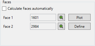
To update faces uncheck the option Calculate Faces automatically.
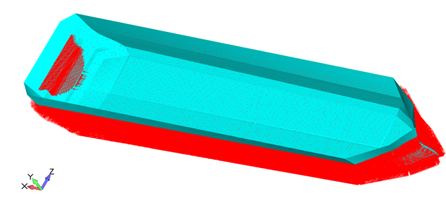
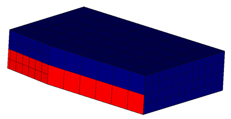
Press to preview the element faces (blue = face1, red = face2):
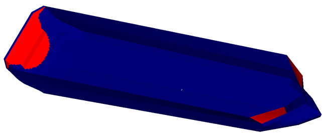
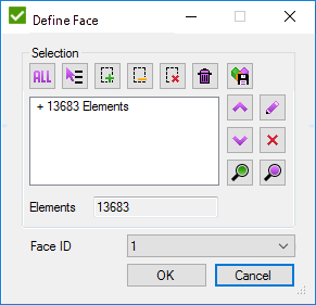
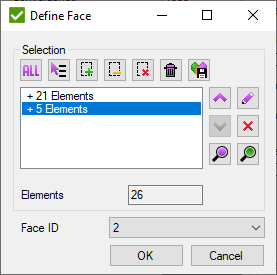
Press to set Face1 for elements with the inside pressures (red color on the picture above):
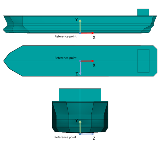
Reference Point is a point which is located in the center of the hull but min vertical coordinate.
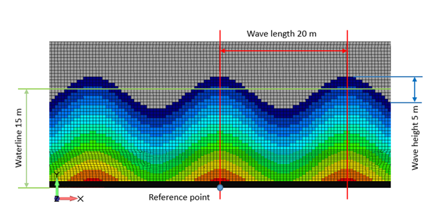
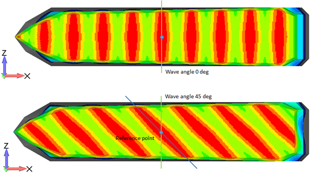
It is also possible to apply buoyancy with the wave:
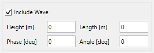
Wave height and length:
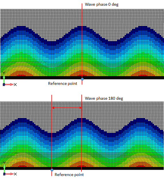
Wave phase:
Wave Angle:
Tank Load
Tank Load gives a possibility to create FEM Loads with pressures acting inside the tank on the plate elements.
To add Tank Load select from the tree:
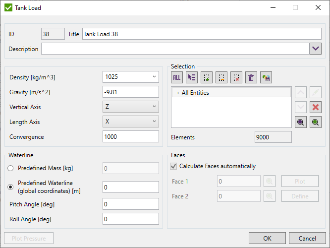
Gravity - gravitation (set by default -9.81 m/s^2).
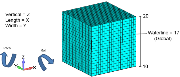
Vertical Axis - waterline is defined for the vertical axis.
Length Axis - longitudinal axis of the ship.
Convergence - is accuracy for balancing when the waterline is calculated using predefined mass.
Fdiff = Pressure_Force - Predefined_Mass * Gravity;
Fdiff^2 < 100*Convergence;
Waterline can be calculated automatically basing on the predefined mass of tank liquid or defined manually (global coordinate). Pitch - the rotation angle around Length Axis and Roll around Width Axis.
Selection - define Tank elements.
Tank Load automatically recognizes the element faces to apply pressure, but the recognition requires a perfectly connected mesh. Otherwise, the tank load can be applied to the wrong side and faces should be modified manually.
Example: Tank with not connected mesh:
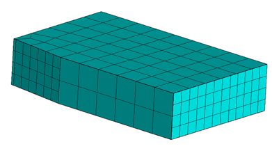
Faces are not recognized automatically and a part of the pressure is applied outside:
To update faces uncheck the option Calculate Faces automatically.
In the current example, all pressures are applied only to Face1. Press to set Face2 for elements with the outside pressures:
Press Plot to preview faces IDs (blue = face1, red = face2):
Press to display the pressure plot of Tank Load (available only when edit Tank Load).
Snow
To create Snow execute from the tree:

Snow Direction, Pressure Value, and Selection should be defined to create Snow load.
For the direction, it is possible to select the Global Axis or define vector by pressing  .
.
Selection should be defined using Selector Control.
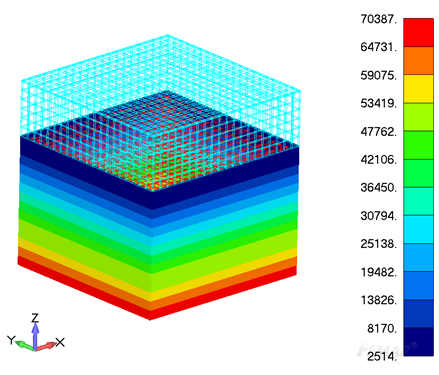
It is possible with the elements to which snow will be applied. If Show Only Selected option is chosen, then the whole model is shown and snow elements are highlighted. Otherwise, only snow elements will be displayed.
Multi Nodal Force
Multi Nodal Force load gives a possibility to apply a load with different nodes magnitudes. Also, few loads can be created at once.
To add Nodal Force Load select from the tree:
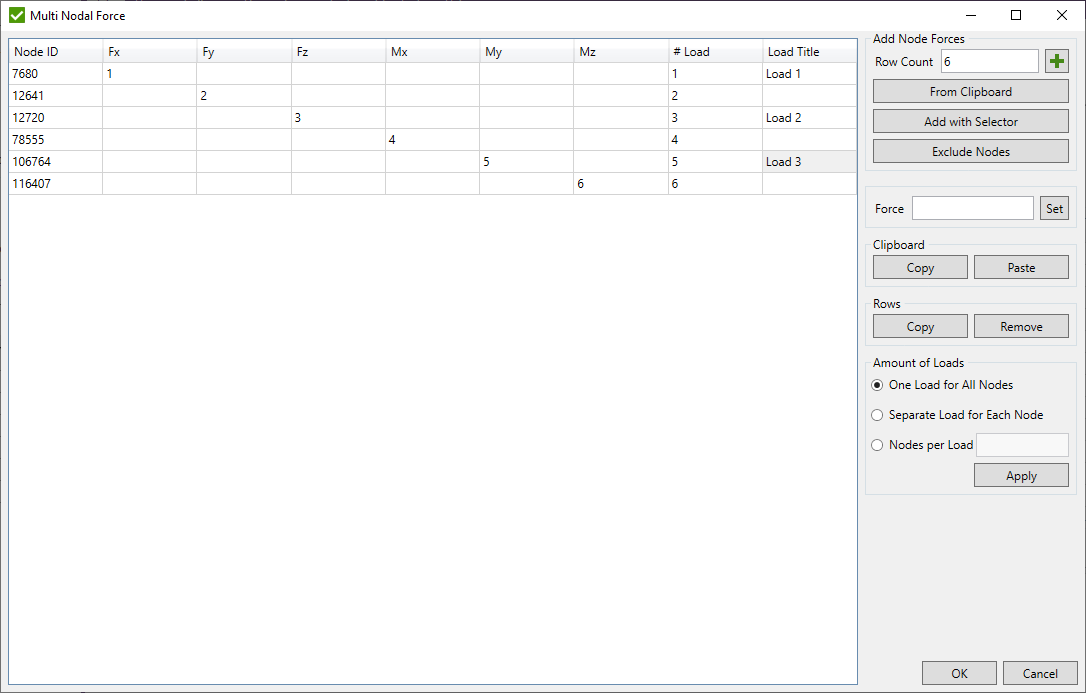
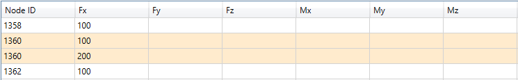
There are 3 ways to define nodes with forces:
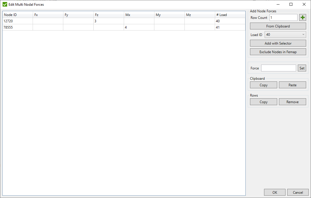
- Add empty rows to the table and fill node ids and force values manually or copy from an external source (Excel/text file). Fill the number of rows in Row Count field and press
 .
. - From Clipboard - add new rows to the table with data from the clipboard (it has to contain only numeric values);
- Add with Selector - add the number of rows to the table = the amount of nodes is defined using Selector Control.
Exclude Nodes - remove nodes from the table by picking nodes in the model.
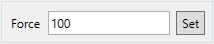
To set the same value for the selected cells input value in the field and press the .
Press to send data from the selected cells to the clipboard.
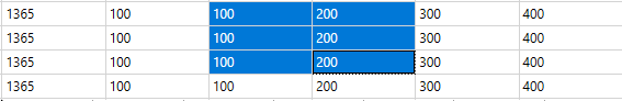
To import data from the clipboard press . All data from the clipboard will be pasted starting from the top left selected cell:
Rows in the table can be copied or removed with buttons or respectively.
With the help of Amount of loads group box it can be controlled how many loads will be created:
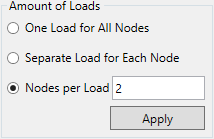
- One load for all nodes:
- Separate load for each node:
- Nodes per load (4 nodes per load in the following example):


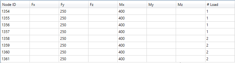
As a result, 2 loads are created:
It is possible to group nodes manually into loads. Fill the same number in # Load column to group nodes into one load.
An invalid number and not existing nodes in the model are highlighted with red when is pressed.
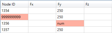
Rows with coincident nodes are highlighted:
Execute from the Fem Loads context menu:
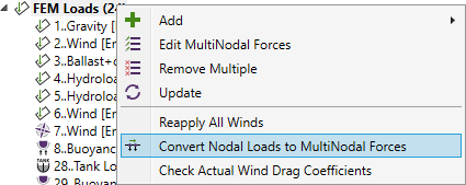
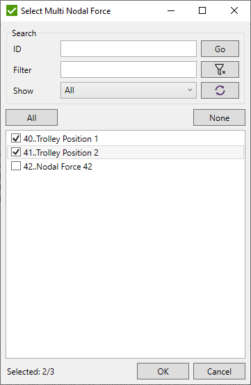
The list of loads that can be converted is shown. Select the loads to convert:
The selected loads that are updated:
Execute from the Fem Loads context menu:
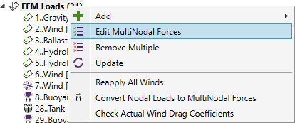
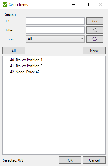
Select the loads to edit:
The editing dialog is very similar to the creation of multimodal forces dialog:
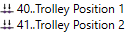
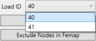
The load Ids can be used only from the list of selected loads:
Nodal Force
Nodal Forces gives a possibility to apply the force, moment, displacement or rotation loads on the selected nodes.
To add Nodal Force Load select from the tree:
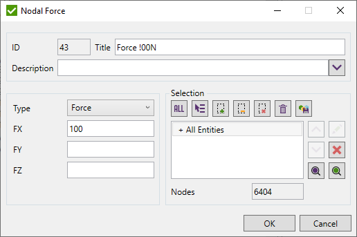
Select nodes using Selector Control.
To apply the load select Type and the values for three directions.
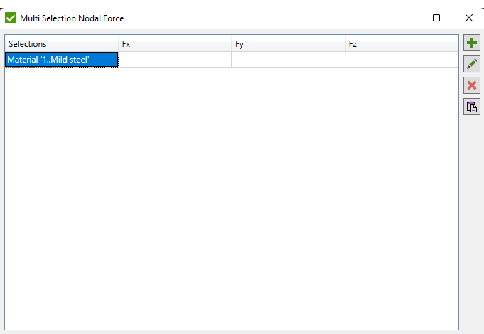
Multi Selection Nodal Force
Multi Selection Nodal Forces gives a possibility to apply the force to different parts of the model by creating multiple Nodal Forces.
To add Multi Selection Nodal Force select from the tree:
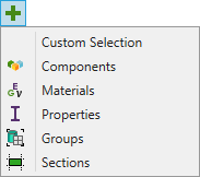
- Custom Selection - add custom selection using Selector Control;
- Components - select Components from the list. Each component will be added as a separate selection;
- Materials - select Materials from the list. Each material will be added as a separate selection;
- Properties - select Properties from the list. Each property will be added as a separate selection;
- Groups - select Groups from the list. Each group will be added as a separate selection;
- Sections - select select sections recognized by Panel Finder Tool from the list. Each section will be added as a separate selection.
Note: Group should contain nodes to proceed.
- edit selected selection;
 - remove selected selections from the list;
 - Paste force values from the clipboard starting from the top left selected cell.
If first column is selected - the first factor from the clipboard will be ignored.
- Paste force values from the clipboard starting from the top left selected cell.
If first column is selected - the first factor from the clipboard will be ignored.