Constraints
Constraint prevents nodes from moving in any of six degrees of freedom (DOF). Constraint is an integral part of the Individual Load.
You can create following constraints:
Nodal
Execute from the tree to add nodal constraint:
To begin, you must first decide on the type of load you intend to create.
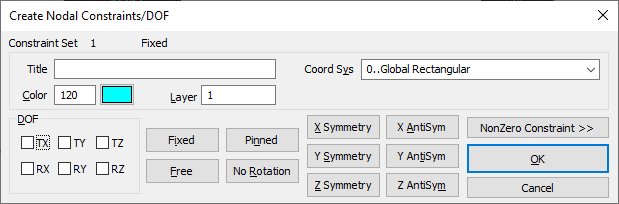
Title - permits to assign a name to the "Constraint Definition" you're creating. If you do not enter a title, a default title will be automatically generated, reflecting the type of constraint that has been established.
Color/Palette and Layer - used to specify the parameters for the nodal constraint that is being created.
Coord Sys - enables to select a coordinate system that will determine the nodal degrees of freedom and, consequently, the directions of the constraints for all the chosen nodes.
Degrees of Freedom - select any combination of the six nodal degrees of freedom (TX, TY, TZ, RX, RY, and RZ) by using the provided check boxes. However, for situations where standard combinations of degrees of freedom are required, you have the convenience of quickly selecting the desired combination by clicking the corresponding command button.
NonZero Constraints
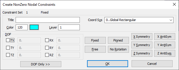
The "Create NonZero Nodal Constraints" dialog box possesses all the features found in the "Create Nodal Constraints/DOF" dialog box, but it additionally includes fields adjacent to each degree-of-freedom (DOF) in the DOF section, where you can enter a numerical value:
Geometric Constraints
You can establish nodal constraints indirectly by constraining geometry. This approach allows automatically apply these constraints to nodes that are linked to the constrained geometry, either through translation or expansion processes.
Geometric constraints are categorized into two types: standard and advanced.
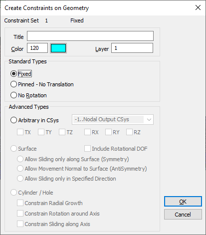
- Standard geometric constraints - provide a simplified approach, allowing you to choose from predefined sets of constraints. These include constraining all translations (DOF 123 - Pinned), all translations plus all rotations (DOF 123456 - Fixed), or all rotations alone (DOF 456 - No Rotation). These constraint combinations are straightforward as they do not necessitate modifications to the nodal output coordinate systems during translation. Hence, they can be applied in any number of constraint sets and in any combination;
- Advanced geometric constraints - offer comprehensive control over the degrees of freedom you wish to constrain. However, this level of control demands more attention during specification because analysis programs typically support only one output coordinate system per node. This means that certain combinations of advanced geometric constraints might not be feasible within a single analysis run.
The geometric constraints, similar to the geometric loads, are divided into four commands: On Point, On Curve, On Surface.
Whether you are defining constraints on points, curves or surfaces, you will see the same dialog box. The Standard constraint types are available at the top of the dialog box. The Advanced types are at the bottom of the box:
On Point
This approach is utilized for applying constraints directly to points, which are subsequently converted into nodal constraints during translation or expansion. Employing this method can simplify the entity selection process, as models usually contain far more nodes than points. However, in many cases, it can be equally straightforward to apply the constraints directly to the nodes themselves.
On Curve
This method is employed to directly apply constraints to curves. You begin by selecting the desired curves using the standard entity selection box, followed by choosing the type of constraint you wish to apply. Nodes that are connected to the selected curve will then be subjected to the specified constraints during translation or expansion processes.
On Surface
This approach is used to directly apply constraints to surfaces. You start by selecting the surfaces using the standard entity selection box, and then choose the type of constraint you wish to impose. Nodes that are attached to the selected surfaces will subsequently be constrained during translation or expansion processes.