Contacts
Contacts contains different entities required to set up contact conditions. There exist 3 types of entities upon which contact can be established:
Contact Properties
Contact property defines details of connector. It can be created by execution
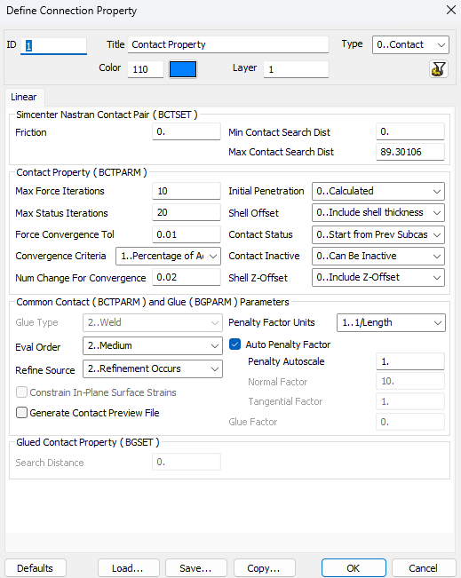
Type
Defines the type of contact that is used. Can be Contact (Regular) or Glued.
Contact Pair
Friction - the static coefficient of friction for contact pair. If varying friction values are unnecessary, all contact pairs should point to the same contact property.
Min Contact Search Dist - the minimum search distance for contact pair. The minimum distance has the potential to be negative and is utilized to represent an interference fit condition where surfaces overlap.
Max Contact Search Dist - the maximum search distance for contact pair. It is necessary to define the maximum distance for all contact problems.
Contact Property
Max Force Iterations - the maximum number of iterations for a (inner) force loop. [Default value is 10]
Max Status Iterations - the maximum number of iterations for a or a (outer) status loop. [Default value is 20]
Force Convergence Tol - the contact force convergence tolerance. [Default value is 0.01]
Convergence Criteria - can be Number of Changes (allowable number of contact changes) or Percentage of Active (percentage of the number of active contact elements)
Num for Convergence - if Convergence Criteria is Number of Changes value must be an integer number greater than 1 else it must be between 0.01 and 0.99.
Initial Penetration - handles initial gap or penetration of the generated contact elements. [Default value is Calculated]
- Calculated - utilize the calculated value from the grid coordinates. When encountering penetrations, employing this option may result in the model exhibiting "press fit" behavior.
- Calculated/Zero Penetrations - same as Calculated, however, if penetration is identified, adjust the value to zero.
- Zero Gap/Penetration - adjusts the penetration/gap to zero for all contact elements.
Shell Offset - set if the shell offset is included or not. Include shell thickness surface offset equals half of shell thickness. [Default value is Include shell thickness]
Contact Status - specify whether the contact status for a particular subcase should begin from the final status of the previous subcase. [Default value is Start from Prev Subcase]
Contact Inactive - indicate if the contact elements can become inactive. Possible values are: Can Be Inactive [Default] or Restrict From Inactive.
Shell Z-Offset - specify whether the shell element z-offset is included in the contact solution. [Default value is Include Z-Offset]
Common Contact and Glue Parameters
Glue Type - indicate the glue formulation. Can be Spring which creates normal and tangential connectors by using Auto Penalty Factor or combination of Normal Factor and Tangential Factor or Weld which creates weld-like connectors using only Glue Factor. [Default value is Weld]
Eval Order - defines the number of linear contact or glue points for a single element on the source region. The higher the value, the more time it will take to solve.
Refine Source - indicates if the source region is refined based on target surface definition.
Constrain In-Plane Surface Strains - defines strains in the plane of the surface being glued in the direction perpendicular to the edge are constrained or not by the glue stiffness.
Generate Contact Preview File - request the export of a bulk data representation of the element edges and faces where glue elements.
Penalty Factor Units - specifies the method for calculating the stiffness of contact elements.
Auto Penalty Factor - indicate automatic calculations of normal and tangential penalty factors.
Penalty Autoscale - scales the automatically calculated normal and tangential penalty factors either up or down and can be used to scale the stiffness of specific contact pairs if convergence issues occur. [Default value is 1.0]
Normal Factor - the penalty factor for the normal direction. [Default values are: Contact type 10.0, Glue type 100.0]
Tangential Factor - the penalty factor for the tangential direction. [Default values are: Contact type = 1.0, Glued type = 100.0]
Glue Factor - the penalty factor when Glue Type is set to Weld. [Default value is 1.0]
Glued Contact Property
Search Distance - determines the distance between contact regions which is used check if the glued contact is active for these regions.
Press to copy parameters from existing contact property.
Contact Regions
Contact region defines individual segment of contact. It can be created by execution
Region`s visibility on the scene can be adjusted using entity visibility control.
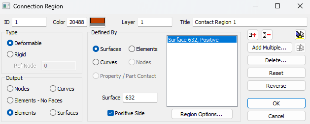
Type
Type of contact region can be Deformable or Rigid. Segments of rigid type requires Ref Node (rigid body reference node) to be set.
Output
Defines output of the segment. Possible options are: Nodes, Elements No-Faces, Elements.
Defined By
Determines entities which region will be created. Possible entities are elements, nodes, surfaces and curves.
Selected model entites are displayed in the list.
Press to define an offset distance.
Connectors
To create connector execute
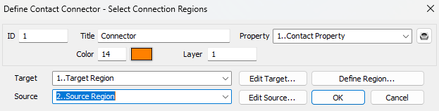
Connector`s visibility on the scene can be changed using entity visibility control.
Select Target and Source contact regions, Contact property to add connector.
 - define new contact property.
Press to edit target region.
Press to edit source region.
Press to create a new region.