Eurocode3 Bolts (EN 1993-1-8, 2005)
Eurocode3 Bolts (EN 1993-1-8, 2005) - Bolt checks according to EN 1993-1-8:2005. Section 3 Connections made with bolts, rivets or pins is implemented.
To add Eurocode3 Bolts standard execute from the ribbon:
Press  to Set Standard Custom Settings
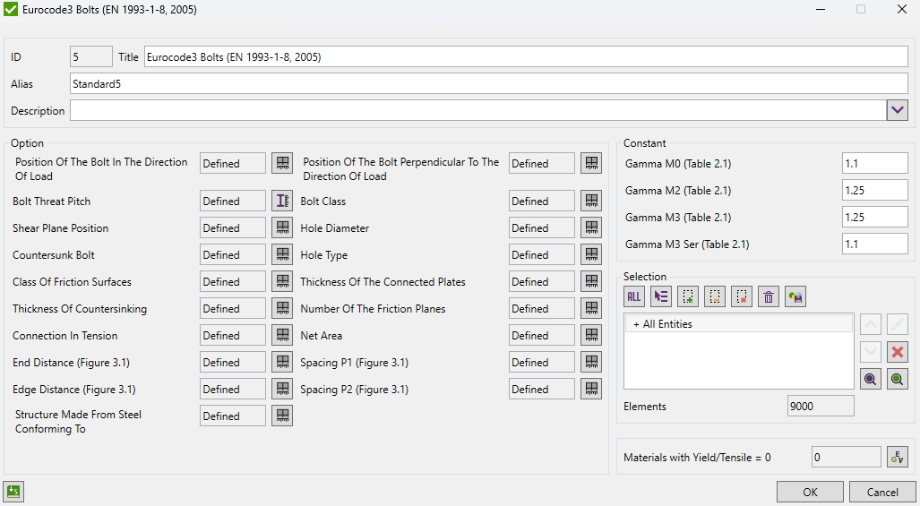
Standard uses material data (Yield/Tensile) in calculations. Wizard checks if the values are defined for all materials.
Position Of The Bolt In The Direction Of Load - end bolts or inner bolts;
Bolt Threat Pitch - the distance between threads in model units;
Shear Plane Position - defines whether shear is passed through the threaded or unthreaded portion of the bolt;
Countersunk Bolt - set if bolt is countersunk or not. Used in Table 3.4 to define coefficient k2;
Class Of Friction Surfaces - used in Table 3.7 to take slip factor for pre-loaded bolts;
Thickness Of Countersinking - for countersunk bolt, the bearing resistance F_bRd should be based on a thickness t equal to the thickness of the connected plate minus half the depth of the countersinking. In model units;
Connection In Tension - set if connection is in tension or not;
End Distance (Figure 3.1) - the end distance from the center of a fastener hole to the adjacent end of any part, measured in the direction of load transfer. Figure 3.1 in model units;
Edge Distance (Figure 3.1) - the edge distance from the center of a fastener hole to the adjacent edge of any part, measured at right angles to the direction of load transfer. Figure 3.1 in model units;
Structure Made From Steel Conforming To - used in Table 3.3: Minimum and maximum spacing, end and edge distances;
Position Of The Bolt Perpendicular To The Direction Of Load - edge bolts or inner bolts;
Bolt Class - class of bolt calculated by the standard. Table 3.1;
Hole Diameter - the hole diameter for a bolt, a rivet or a pin. In model units;
Hole Type - used for taking values of kS in Table 3.6;
Thickness Of The Connected Plates - thickness of the connected plates. In model units;
Number Of The Friction Planes - the number of the friction surfaces or the number of fastener holes on the shear face;
Net Area - net area;
Spacing P1 (Figure 3.1) - the spacing between centres of fasteners in a line in the direction of load transfer. Figure 3.1 in model units;
Spacing P2 (Figure 3.1) - the spacing measured perpendicular to the load transfer direction between adjacent lines of fasteners. Figure 3.1 in model units;
Gamma M0 - partial safety factor for members and cross-sections. Table 2.1.
Gamma M2 - partial safety factor for bolts. Table 2.1.
Gamma M3 - partial safety factor for slip resistance at ultimate limit state (Category C). Table 2.1.
Gamma M3 Ser - partial safety factor for slip resistance at serviceability limit state (Category B). Table 2.1.